Table of Contents
Advertisement
Advertisement
Table of Contents

Subscribe to Our Youtube Channel
Summary of Contents for Simco-Ion scorpION3
- Page 1 Ionizing Bar System scorpION3 User’s Manual...
- Page 2 Simco-Ion Technology Group is a division of Illinois Tool Works (ITW), located in Alameda, California. For more information about Simco-Ion visit www.simco-ion.com or call 800-367-2452.
- Page 3 User supplied 24 VDC power must conform to the electrical characteristics as outlined in this document. Incorrect power connections to the bar can result in damage to the scorpION3 bar and/or to user power supply. User connections to the fault output must conform to the limita- tions outlined for the opto-isolated transistor.
- Page 4 Utilisateur fourni alimentation 24 VCC doit être conforme aux caractéristiques électriques tel que décrit dans le présent docu- ment. Mauvaise connexion de l'alimentation de la barre peut entraîner des dommages au scorpion3 bar et/ou à l'utilisateur d'alimentation. Connexions de l'utilisateur à la sortie de panne doivent être conformes aux limites décrites pour l'opto-isolées le transistor.
-
Page 5: Table Of Contents
Contents 1 Description ................1 1.1 scorpION3 Ionizing Bar System............... 2 1.2 Features....................4 2 Installation ................5 2.1 Mounting Considerations ................. 6 2.2 Wiring Considerations................7 2.3 Bar Configuration .................. 10 2.4 Multi-Bar Installations................11 2.5 Air Assist (optional) ................12 2.6 MMI (Man Machine Interface) .............. -
Page 6: Description
Description 1.1 scorpION3 Ionizing Bar System 1.2 Features scorpION3 5200969 Rev 4... -
Page 7: Scorpion3 Ionizing Bar System
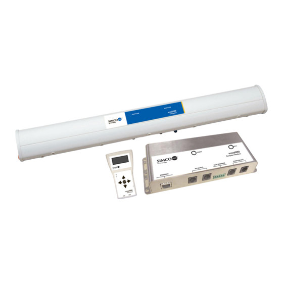
1.1 scorpION3 Ionizing Bar System The scorpION3 bar system is an ionization solution for work areas and OEM mini-environments. Intended for cleanroom applications, the bar is available with tungsten or single crystal silicon emitter points for the cleanest ionization available. scorpION3’s flexible design allows independent or dependent operation of multiple bars in a system. - Page 8 A scorpION3 bar may be designated as a master; it will then talk to the other bars connected to it via integrated RS-485 communication. The master maintains contact with each bar to synchronize system operations. Individual bars connected in a system monitor and store their own operating parameters.
-
Page 9: Features
• Detects address conflicts on bus, allows user to resolve CI – Computer Interface • Provides Ethernet connection for networking • Remote set-up, monitoring and control • Connection to other scorpION3 computer interfaces • Automatically addresses and resolves bar address conflicts scorpION3 5200969 Rev 4... -
Page 10: Installation
Installation 2.1 Mounting Considerations 2.2 Wiring Considerations 2.3 Bar Configuration 2.4 Multi-Bar Installations 2.5 Air Assist (optional) 2.6 MMI (Man Machine Interface) 2.7 CI (Computer Interface) scorpION3 5200969 Rev 4... -
Page 11: Mounting Considerations
Prior to powering up a single or multi-bar system, the ionizing bar(s) should be securely mounted using the provided hardware. If the scorpION3 bar is mounted using hardware not provided with the unit, it is important to keep any grounded hardware away from the emitter tips. -
Page 12: Wiring Considerations
3 & 4 to ground (ground serving as the return for the supply voltage), see table below. Users connecting to the scorpION3 in this method must be able to supply 200mA per bar connected. scorpION3 5200969 Rev 4... - Page 13 The scorpION3 is internally fused to protect the user’s power supply during this type of setup. Le scorpION3 est à fusible interne afin de protéger l'utilisateur d'alimentation pendant ce type de configuration. RJ-11 MODULAR CONNECTOR PIN NUMBER CONNECTION +24 VDC N.C.
- Page 14 The fault output transistor may be used to provide switching in order to drive a variety of low current devices such as LEDs or buzzers, relays may be used to switch power to higher power devices. scorpION3 5200969 Rev 4...
-
Page 15: Bar Configuration
The scorpION3 bar has two ionization indicators and a window for receiving and transmitting commands via IR with the MMI, incorporated into the scorpION3 face label on the front of the bar. The indicators have multiple functions. The main function of the indicator is to illuminate when the high voltage power supply is activated. -
Page 16: Multi-Bar Installations
9 bars may be connected to the master. In cases where a combination of steady state and pulse coverage is required with multiple bars, a bar or bars within the system can be set to the independent class. scorpION3 5200969 Rev 4... -
Page 17: Air Assist (Optional)
2.5 Air Assist (optional) If the scorpION3 bar has Air Assist, the inlet fitting will be located on the end of the bar with the fault output jack. This fitting is a ¼” quick connect suitable for typical plastic tubing (1/4”OD polyethylene, polyurethane, nylon, etc). -
Page 18: Mmi (Man Machine Interface)
2.6 MMI (Man Machine Interface) Adjustments to ion balance and ion output can be made to the scorpION3 bar system by using the hand-held MMI. The MMI features a 4-line LCD display for setting the bar parameters and monitoring its operation. The MMI uses an infrared transceiver for two-way communication with the bar in IR Mode. - Page 19 Bar or Preset. If Bar is selected the MMI will prompt the user to point the MMI at the bar and press enter. The MMI and scorpION3 bar feature narrow angle IR transceivers to minimize undesired IR cross talk. It will be necessary to align the MMI and bar IR transceivers to ensure communication.
- Page 20 Advancing into the Wired mode will cause the MMI to search the scorpION3 system and determine the number of bars present; the number of bars in the system will be displayed. When the MMI has...
- Page 21 This is more typically used where there is airflow to carry the ions to the target. • Slave/Independent (default: independent) allows for selection of the bar as a Slave (non-0 address only) or Independent. scorpION3 5200969 Rev 4...
- Page 22 • Fault Threshold (default 20) is the relative number of times the microprocessor must encounter a fault condition before it signals the fault state. Using a threshold to trigger a fault state reduces nuisance alarms. Increasing the threshold reduces the scorpION3 5200969 Rev 4...
- Page 23 MMI menu to the Feedback screen. • PRG Metered feedback ‘Program’ is the input value to the ion regulating circuitry as established by the microprocessor. There is a ‘Program’ value for the positive and negative high scorpION3 5200969 Rev 4...
- Page 24 (second two digits. The threshold values are in hexa- decimal. ‘R:000’ provides a “snapshot” of which accumulators are above threshold value. ‘00’” indicates accumulated fault codes, in this case, no accu- mulation. The accumulator bins indicate fault codes as follows: scorpION3 5200969 Rev 4...
- Page 25 At the end of setting the preset the preset number (P1 through P14) may be assigned and the preset saved.
-
Page 26: Ci (Computer Interface)
2.7 CI (Computer Interface) The scorpION3 CI (Computer Interface) provides an interface between the scorpION3 bar system and a personal computer or local computer network via Ethernet connection. With Simco-Ion’s monitor software, a user may set-up, monitor or control the scorpION3 bar system from their computer. - Page 27 24 VDC via the plug type terminal block labeled user interface. Connect pin 1 to ground/return and pin 2 to +24 VDC. NOTE: Users connecting to the scorpION3 in this fashion must supply 200 mA per each bar connected plus 100 mA for the computer interface and 50 mA for a hardwired MMI.
- Page 28 Interface provides continuous monitoring of the bar system set-up and operating parameters, the ability to adjust parameters and display of diagnostic information. Detailed information on the Computer Interface and software is available in publication 5200968, scorpION3 Monitor Software user manual. scorpION3 5200969 Rev 4...
- Page 29 5200969 Rev 4...
-
Page 30: Operation
Operation 3.1 Settings scorpION3 5200969 Rev 4... -
Page 31: Settings
“save settings local to bar”. Setup Recommendations Factory default settings for the scorpION3 are for a typical tool or mini environment installation with the scorpION3 bar installed under the filter fan / top of the unit and a target distance of approximately 600 mm (24”). - Page 32 ANSI/ESD STM 3.1-2006 Ionization, Section 6.2 laminar flow hood ionization. A Charge Plate Monitor that meets the requirements of ESD STM 3.1 should be used for this purpose. scorpION3 5200969 Rev 4...
- Page 33 During normal operation, the Positive Ion and Negative Ion indicators on the scorpION3 face label will glow green. If the bar is in the steady state mode, the indicators will glow continuously. If the bar is in the pulse mode, the indicators will flash alternately (with both on during overlap), indicating ion output.
-
Page 34: Maintenance
Maintenance 4.1 Cleaning & Calibration 4.2 Cleaning the Emitters 4.3 System Calibration 4.4 System Diagnostics scorpION3 5200969 Rev 4... -
Page 35: Cleaning & Calibration
The scorpION3 bar is designed to require minimum maintenance, cleaning, and calibration. There are no user serviceable parts within the scorpION3 bar. No attempt should be made to disassemble or repair defective products. Please contact Simco-Ion customer service for information concerning repair or replacement. -
Page 36: Cleaning The Emitters
4.2 Cleaning the Emitters Simco-Ion emitters have a serviceable life of three or more years in a typical cleanroom environment when operated in conjunction with a regular maintenance program. Evaluation of emitter condition should be considered when cleaning the emitters. Worn emitter replacement can be performed as part of a scheduled cleaning and calibration. - Page 37 Clean all the emitter electrode points. 4. The bar housing can be cleaned using a cleanroom wiper or soft cloth as appropriate. scorpION3 5200969 Rev 4...
- Page 38 5. Allow all alcohol to evaporate before applying power to the bar. 6. It is recommended practice to develop a regular cleaning schedule that meets your requirements and operating condi- tions. scorpION3 5200969 Rev 4...
-
Page 39: System Calibration
Test data should include temperature, humidity, and air velocity. Tests of the system are made in accordance with ANSI/ ESD STM 3.1-2006 Ionization, Section 6.2 laminar flow hood ionization. Contact Simco-Ion for information concerning test instruments and services. scorpION3 5200969 Rev 4... -
Page 40: System Diagnostics
The system diagnostics can be accessed through the MMI by wired or IR communication with the scorpION3 bar. When the diagnostic menus are entered, the MMI downloads settings and operating data from the bar. This information is displayed in a series of menus on the MMI. - Page 41 5200969 Rev 4...
-
Page 42: Specifications
Specifications 5.1 Specifications 5.2 Parts & Accessories scorpION3 5200969 Rev 4... - Page 43 Stainless steel brackets, with universal adjustable mounting centers. Mounting Clamping thumbscrew Integrated #8-32 mounting nut Enclosure Reinforced Polycarbonate 457 mm (18”); 610 mm (24”); 914 mm (36”); 1118 mm (44”); 1626 mm (64”); Dimensions 1880 mm (74”); 2134 mm (84”) scorpION3 5200969 Rev 4...
- Page 44 2.2 kg (4.9 lb); 2.5 kg (5.5 lb) Warranty Two year limited warranty Certifications RoHS 2 Compliant scorpION3 Bar with Air Assist Air Inlet ¼” QC Tube Fitting Input Pressure 200 kPa (30 psi) recommended nominal, 700 kPa (100 psi) max, CDA 5.1 Nm3/h @ 200 kPa (3 scfm @ 30 psi);...
- Page 45 LED Indicators Green POWER; red FAULT Dimensions 84 x 211 x 34 mm (3.30 x 8.30 x 1.35 in.) Enclosure Stainless Steel Software Windows 2000, Windows XP, Windows 7 1. Tested in accordance with ANSI/ESD STM3.1-2006. scorpION3 5200969 Rev 4...
- Page 46 74" ScorpION3 Ionizing Bar, Nineteen (19) Tungsten (W) emitters 4011552 84" ScorpION3 Ionizing Bar, Nineteen (19) Tungsten (W) emitters 4015461 18" ScorpION3 Ionizing Bar w/Air Assist, Seven (7) Ultraclean Silicon emitters 4015462 24" ScorpION3 Ionizing Bar w/Air Assist, Seven (7) Ultraclean Silicon emitters 4015463 36"...
- Page 47 ScorpION2/3 AC Adapter, 24 VDC Out, 100-240 VAC Universal Input with United 5051330 Kingdom (BS 1363) Line Cord 4107405 Mounting Bracket with integrated 8-32 nut 4107878 Mounting Bracket with clearance hole for M4 or M5 (#8 or #10) screw scorpION3 5200969 Rev 4...
-
Page 48: Warranty & Service
Bar. New products manufactured or sold by Simco-Ion are guaranteed to be free from defects in material or workmanship for a period of two (2) years from date of initial shipment. Simco-Ion liability under its new product warranty is limited to servicing... - Page 49 5200969 Rev 4...
- Page 50 Appendix A MMI Navigation Reference Guide START: Splash screens: Simco-Ion, software version, display test, indicator LED test. WIRED MODE *select mode (wired or address test) *wired *searching *select bar, preset, or sysmon *bar scroll list (LEDs on selected bar flash)
- Page 51 (MMI LED’s indicate bar fault status). IR MODE NAVIGATION *select bar or preset IR ACQUISITION (1st READBACK) *Point MMI at bar & press enter *accept bar address *select settings or diagnostics IR SETTINGS NAVIGATION power output pulse/steady state slave/independent 1 scorpION3 5200969 Rev 4...
- Page 52 & right jump to fault status accumulators down & left jump to feedback (program, current , drive monitors) left & right jump to balance adjustment * Hot Keys are NOT enabled scorpION3 5200969 Rev 4...
- Page 53 Check emitter housing & emitter currently set). electrode seating. Ion Output Too Emitters need cleaning. Reduce Ion Output setting. Emitter housing or emitter Replace emitter electrodes. electrode not seated. Replace HV supplies. HV open circuit. Replace bar. HV supplies faulty. scorpION3 5200969 Rev 4...
- Page 54 Replace bar. Replace I/O board. Feedback Error I/O Board fault. Replace bar. Must be interpreted by a Multiple Fault Replace bar. Simco-Ion technician. Communication Fault in RJ-11 connectors Check connections and modular Fault or modular cable. cable. scorpION3 5200969 Rev 4...
- Page 55 Notes scorpION3 5200969 Rev 4...
- Page 56 Technology Group 1601 Harbor Bay Pkwy, Ste 150 Alameda, CA USA 94502 Tel: 510-217-0600 Fax: 510-217-0484 Toll free: 800-367-2452 Sales services: 510-217-0460 Tech support: 510-217-0470 ioninfo@simco-ion.com salesservices@simco-ion.com techsupport@simco-ion.com service@simco-ion.com www.simco-ion.com scorpION3 5200969 Rev 4...
Need help?
Do you have a question about the scorpION3 and is the answer not in the manual?
Questions and answers