Table of Contents
Advertisement
PLEIGER ELECTRONICS
Manual
Operation
Installation
Connection
Technical data
Hardware extensions
Functional extensions
Commissioning help
Edition: 6/2007
Subject to modifications
Pleiger Elektronik GmbH & Co. KG
D-58456 Witten - Im Hammertal 51
D-58423 Witten - P.O.Box 32 63
Telephon +49 (0) 23 24 * 3 98- 0
Telefax
+49 (0) 23 24 3 98- 3 89
www.pleiger-elektronik.de
info@pleiger-elektronik.de
362MC
Advertisement
Table of Contents

Related Manuals for pleiger 362MC

Summary of Contents for pleiger 362MC
- Page 1 Hardware extensions Functional extensions Commissioning help Edition: 6/2007 Subject to modifications Pleiger Elektronik GmbH & Co. KG D-58456 Witten - Im Hammertal 51 D-58423 Witten - P.O.Box 32 63 Telephon +49 (0) 23 24 * 3 98- 0 Telefax +49 (0) 23 24 3 98- 3 89 www.pleiger-elektronik.de...
-
Page 2: Table Of Contents
Connection with floating switching output contacts ...... 30 Connection of the alarm output ............... 31 Connection of the binary inputs ............... 31 Connection of the remote resistance-type sensor ........31 Page: 2 Manual for 362MC Edition: 6/2007 Subject to modifications... -
Page 3: Appendix C: Functional Extensions For The 362Mc
Appendix A4: Error displays and messages from A to Z ........37 Appendix A5: Symbols employed in this manual ..........37 Appendix B: Hardware extensions for the 362MC Appendix B1: Hardware extension - 2 relay set ..........38 Appendix B2: Hardware extension - Analogue outputs ........ -
Page 4: Introduction
• difference input for actual values, e.g. for differential pressure control of pumps. In the appropriate configuration, the single 362MC unit is thus able to replace the Pleiger controllers and supplementary modules 361-D, 362-D, 366-D and 366-V. Page: 4... -
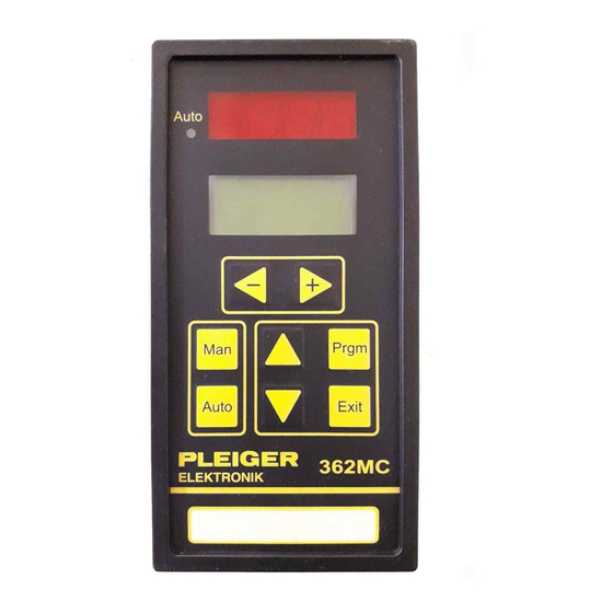
Page 5: Display And Operating Elements
For special applications, the display is also available as a 3½-digit variant (with decimal digit or for special measuring ranges). The 362MC additionally features an two lines LCD process data and parameter display. During normal operation of the controller, this display is employed to display various process variables. -
Page 6: Display
60 seconds during the selection or entry process, the operational display will be re-activated automatically. Parameter On power up, the 362MC always displays the type and version no. Page: 6 Manual for 362MC Edition: 6/2007 Subject to modifications... -
Page 7: Operating Modes
GmbH & Co. KG Operating modes The 362MC incorporates two operating modes - Automatic and Manual / Emergency manual mode. A modified menu is provided for each operating mode. Both operating modes offer an extended version of the menu for commissioning purposes. This extension to the menus for configuration and parameterisation of the controller is protected by a password to prevent unauthorised use. -
Page 8: Switching Between Manual/Automatic
1 controller in Emergency manual mode, and have no other functions. Page: 8 Manual for 362MC Edition: 6/2007 Subject to modifications... -
Page 9: Commissioning Extension
GmbH & Co. KG Commissioning extension The menu selection option of the 362MC can be extended for the purposes of commissioning the con- troller. The extended functions for altering the configuration or parameterisation are available in both Automatic and Manual / Emergency manual mode. The menu extension is accessible after entering the password. -
Page 10: Edition: 6/2007 Subject To Modifications
Digit 2 to 4 entered as already described in Value entry detail under ‘Password entry’. Any number >=0000 and <=9999 is save permissible as the value for the password. password Page: 10 Manual for 362MC Edition: 6/2007 Subject to modifications... -
Page 11: Additional Menu Selection With Quickset
5.1 Additional Menu selection with QuickSet for Controller 362MC from SER.NO 0605 An additional parameter menu is integrated in the Controller 362MC from Serial-No 0605 (Delivery the from middle of 2006) and includes the most important adjustments for the commissioning of the control process. -
Page 12: Commissioning Menu
Many of the range limits (min/max value) stated in the following tables are dependent on the scaling selected for the physical variables via the parameters Scale-0 and Scale-F. See also explanatory note on scaling (5.6.2). Page: 12 Manual for 362MC Edition: 6/2007 Subject to modifications... -
Page 13: Setpoint Menu
We urgently recommend you to alter the parameters marked with the symbol in the tables belonging to this description in “Manual mode only. This will avoid ” unintentional activation of the actuator. Manual for 362MC Page: 13 Edition: 6/2007 Subject to modifications... -
Page 14: Explanatory Note On Setpoints
-1 to 5 bar -1,0 B -1,0 - 5,0 bar configuration for the Displacement sensor 0 to 300 mm 300,0 mm 0 - 300,0 mm installed 362MC is to be Rotation angle sensor 0 to 100% 100,0 % 0 - 100,0 % observed. -
Page 15: Controller Profile Menu
“Prof-No” and its parameters are subsequently displayed and altered in the following menus. Selection and entry points are marked accordingly on the display of the 362MC. The tables belonging to this description state which parameters are stored in which control menu. Parameter... -
Page 16: Controller Parameters Menu
GmbH & Co. KG 5.5 Controller parameters menu This menu includes all the control-related parameters of the 362MC. In this menu the controller type “CtrlTyp” is defined, the parameter set “ParSet” to be displayed and possibly altered is selected and the structure of the controller “Struct” is set. -
Page 17: Explanatory Note On Controller Types
GmbH & Co. KG 5.5.1 Explanatory note on controller types The controller type “CtrlTyp” can be defined separately for each of the 362MC´s two controllers. 2-Point controller = switching controller with 2 switching output states, relay+ ON and relay+ OFF. -
Page 18: Edition: 6/2007 Subject To Modifications
3-Point output with feedback. It is thus only suitable for use in combination with integrating actuators, such as motor actuators. (The operational characteristics of “Step” correspond to those of Pleiger controller 362-D) Controller 362MC Typ: Step... -
Page 19: Explanatory Note On Controller Structure
PID controller (PI controller with added D component) PID2 controller (PI controller with added D2 component) Regarding the D component, see also: Special function - Trend compensation (Appendix C1). Tv/Vd Manual for 362MC Page: 19 Edition: 6/2007 Subject to modifications... -
Page 20: Explanatory Note On Controller Output Parameters
OFF command of 2-Point and 3- Point outputs without feedback. See also Cont Hyst Hysteresis Hy for ON commands of 2-Point and 3-Point outputs without feedback. Page: 20 Manual for 362MC Edition: 6/2007 Subject to modifications... -
Page 21: Input Menu
Ymax 5.6 Input menu In the Input menu, the physical inputs of the 362MC are assigned to the various internal input variables. This assignment is to be defined separately for each profile and thus for each of the two controllers of the 362MC. Double assignments are possible, such as assignment of external input “E1”... -
Page 22: Explanatory Note On Calibration
Pleiger Elektronik GmbH & Co. KG The following table presents an example of assignment of the physical inputs of the 362MC which would correspond to the functions of a 362-D. Parameter Value Meaning ActValX ActValX ActValX PT100-1 PT100-1 PT100-1 ActValX... -
Page 23: Output Menu
This assignment is to be defined separately for each profile and thus for each ofthe two controllers of the 362MC. Double assignments are not expedient and are thus not permissible for entry. The following table shows the assignments for controller output and actual-value output. -
Page 24: Display Menu
Analogue output ActV X Controlled system 362MC Switching Controller Controller output Actuator Setp W Out+Y Feed Y (primary) (secondary) Part A Part B Out%Y Analogue output ActV U ActV X Page: 24 Manual for 362MC Edition: 6/2007 Subject to modifications... -
Page 25: Monitoring Functions And Error Messages
This error may occur when the parameters are loaded during the programme start or during commissioning, when loading profiles, for example. The controller programme cannot be started. When this error applies, the 362MC loads the factory presets as a precautionary measure. Please check urgently, in the following order: - the profiles of both controllers - incorrect profiles will be reloaded after entering the correct profile no.;... -
Page 26: Explanatory Note On The Reset Function For The Controller
6.1.4 Explanatory note on Watchdog error The 362MC incorporates a programme run monitoring function. The correctly running controller programme regularly resets a watchdog timer. Should deviations occur during execution of the programme, e.g. as a result of major external EMC disturbances, this resetting pulse will not be transmitted for the timer. -
Page 27: Service Interface
GmbH & Co. KG Service interface The 362MC possesses a service interface which is accessible on the front of the controller. This inter- face provides for more user-friendly operation and diagnosis of the controller. To this end, a PC and the 362MC service programme “McDiag”... -
Page 28: Installation
GmbH & Co. KG Installation The 362MC controller is delivered in a housing for installation in a control panel in accordance with DIN 43700. The housing dimensions are 144 x 72 mm. 1 2 3 4 5 6 7 8 9 0 1 2 3 4 5 6 7 8 9 0 1 2 3 4 5 6 7 8 9 0 1 2 1 1 2 3 4 5 6 7 8 9 0 1 2 3 4 5 6 7 8 9 0 1 2 3 4 5 6 7 8 9 0 1 2 1 The required control panel cut-out is shown in the diagram. -
Page 29: Connection
GmbH & Co. KG Connection The connection points on the 362MC are grouped together on two screw-/plug terminals on the backside of the controller. The voltage supply, the switching outputs, the alarm and the binary inputs are connected via a 20-pole plug terminal; the analogue inputs and the signals from supplementary modules are connected via an 18-pole plug terminal. -
Page 30: Connection Of Supply Voltage
4.0 AT 9.3 Connection of the switching outputs In standard configuration, controller 362MC has one relay set, consisting of relay+ and relay-, as its switching output. A 2 relay set is available as a hardware extension. Two variants apply for connection of the switching voltage. -
Page 31: Connection Of The Alarm Output
The max. common-mode voltage is +2V. Voltage input 362MC U= 0-10V The 362MC is also available in a special version with a 0-5V voltage input for 0-10V or 0-5V. The appropriate hardware configuration is to be observed here. See also Commissioning menu - Input (5.6) -
Page 32: Connection Of The Pt100 Sensor
Pleiger Elektronik GmbH & Co. KG 9.8 Connection of the PT100 sensor 362MC In the standard configuration of the 362MC, the and 2 analogue inputs serve as PT100 inputs. Connection is effected via a three-wire connection, whereby the compensation for the line resistance of 3 wires is based on 3 wires of the same cross- section and the same length. -
Page 33: Technical Data
0(4) - 20mA, ±20mA 0 - 10V, ±10V Resolution 40µA 20mV Accuracy ±0.5% Load impedance max. 400 Ohm min. 1 kOhm Communication interface (hardware extension) Type RS485 isolated RS422 isolated Manual for 362MC Page: 33 Edition: 6/2007 Subject to modifications... -
Page 34: Appendix A1: Overview Of Menu Structure For Standard Functions
2Setp B 2Setp B 2Alarm- 2Alarm- 2Alarm- 2Alarm- 2Alarm- 1SollwA 1SollwA 1SollwA 1SollwA 1SollwA 2Alarm+ 2Alarm+ 2Alarm+ 2Alarm+ 2Alarm+ Figure shows all possible displayed parameters; displayed parameters dependent on parameterised function! Page: 34 Manual for 362MC Edition: 6/2007 Subject to modifications... -
Page 35: Appendix A2: Parameters From A To Z For Standard Functions
Min. switching duration CtrlPar Derivative action time CtrlPar Max. D gain CtrlPar Ymax Ymax Ymax Ymax Ymax Max. Controller output CtrlPar Ymin Ymin Ymin Ymin Ymin Min. Controller output CtrlPar Manual for 362MC Page: 35 Edition: 6/2007 Subject to modifications... -
Page 36: Appendix A3: Value Assignments From A To Z For Standard Functions
4-20mA Input Lin ..4 Lin ..4 Lin ..4 Lin ..4 Lin ..4 analogue input as 20-4mA Input Manual Manual Manual Manual Manual Internal state: Manual mode Input Dimension millimetre Input Page: 36 Manual for 362MC Edition: 6/2007 Subject to modifications... -
Page 37: Appendix A4: Error Displays And Messages From A To Z
Values stored in profile of controller 1 or 2 Value X in 1 or 2 parameter set of a controller Please alter values in Manual mode only! Particularly important information Manual for 362MC Page: 37 Edition: 6/2007 Subject to modifications... -
Page 38: Appendix B1: Hardware Extension - 2 Nd Relay Set
GmbH & Co. KG Appendix B1: Hardware extension - 2 relay set The hardware of the 362MC can be extendet at the factory via the addition of a 2 set of switching output relays, comprising one relay+ and one relay-. Terminal assignments... -
Page 39: Appendix B2: Hardware Extension - Analogue Outputs
Appendix B2: Hardware extension - Analogue outputs A module incorporating 2 analogue outputs is available as a hardware extension for the 362MC which can be installed at the factory. The module incorporates the respective D/A converters and the isolated output stages, which in standard configuration are provided as linear current outputs. Linear voltage out- puts are also available as a special variant. -
Page 40: Appendix B3: Hardware Extension - Rs485/Rs422 Communication Interface
Appendix B3: Hardware extension - RS485/RS422 communication interface A module incorporating a communication interface is available for the 362MC, for installation at the factory. The interface is isolated, and in the standard version it is wired up as an RS485 interface (2-wire). -
Page 41: Appendix C1: Special Function - Trend Compensation
Appendix C1: Special function - Trend compensation The standard software of the 362MC incorporates a special function for the enhanced control of systems with large dead times. This special trend compensation function, a traditional feature of Pleiger controllers, enables the differential activation of a second measuring sensor. - Page 42 (parameter Trend = PT100-2). 362MC Setp W Out+Y 3-Point step controller 1Relay ActV X Tend D PT100-1 PT100-2 PT100 PT100 Main engine Cooler Page: 42 Manual for 362MC Edition: 6/2007 Subject to modifications...
-
Page 43: Appendix C2: Functional Extension - Disturbance Compensation
Appendix C2: Functional extension - Disturbance compensation The standard functions of the 362MC software can be extendet by additional software, which is to be installed at the factory. Necessary internal hardware extensions, such as extensions to memory areas, etc. are installed at the same time. - Page 44 When a scale from 0-200°C applies, a 1.0% weighting for the disturbance compensation function (Z) will thus correspond to a setpoint increase of 2.0°C. Page: 44 Manual for 362MC Edition: 6/2007 Subject to modifications...
- Page 45 Disturbance compensation is not expedient with the 3-Point step controller, either, and is thus not implemented in the 362MC. Selecting this function for controller type “Step” will have no effect. A 3-Point step controller with setpoint compensation can be implemented via special parameterisation of a “CscStep”...
- Page 46 - 3.5 - 7.0 73.0 - 8 % - 16°C The values for Setp V apply for Setp W=80.0°C, - 10 % - 20°C =1 and Setp W=ActV X (Y=0 compensated). Page: 46 Manual for 362MC Edition: 6/2007 Subject to modifications...
-
Page 47: Appendix C3: Functional Extension - Setpoint Programme
Appendix C3: Functional extension - Setpoint programme The standard functions of the 362MC software can be extendet by additional software in the form of the Setpoint programme, which is to be installed at the factory. Necessary hardware extensions, such as ex- tensions to memory areas, etc., are carried out at the same time. - Page 48 * If a setpoint programme is selected via “SpPrgNo” in order to carry out changes to the programming of the steps and if this programme has been activated under 1SpTypA, 1SpTypB, 2SpTypA or 2SpTypB, the changes should be carried out in manual mode only. Page: 48 Manual for 362MC Edition: 6/2007 Subject to modifications...
- Page 49 1. Line: StpPrg1 in step 4 the run of the setpoint between the different steps. 2. Line: current setpoint (1Setp W) Example controller 2 1. Line: SwPrg3 in step 15 2. Line: controller output (2Feed+y) Manual for 362MC Page: 49 Edition: 6/2007 Subject to modifications...
- Page 50 Example The functions of the setpoint programme are illustrated below by reference to a possible application for the 362MC functional extension Setpoint programme in conjunction with changeover to a 2 setpoint. In this example, the speed of a motor is to be selectable in two speed ranges, fast and slow, via a changeover selector.
-
Page 51: Appendix C4: Functional Extension - Differential Actual Value
Appendix C4: Functional extension - Differential actual value The standard functions of the 362MC software can be extendet by additional software, which must be installed at the factory. Necessary internal hardware extensions, such as extensions to memory areas, etc. are installed at the same time. -
Page 52: Appendix D1: Steps For Commissioning
Appendix D1: Steps for commissioning The 362MC controller incorporates profile memories whose parameters have been pre-parameterised at the factory for commissioning. This factory set-ups are based on decades of experience in controller applications. Using the profile memories will place these experiences at your disposal and save your commissioning time. -
Page 53: Appendix D2: Profile Memories And Factory Presets
4-20mA - and Functional extension - Differential actual value - required< Please use a copy of sheet Prof-No 1 to document your settings and changes. All current Profiles you will find at www.pleiger-elektronik.de/downloads Manual for 362MC Page: 53 Edition: 6/2007 Subject to modifications... - Page 54 0.0% 0.0% 0.0% ⌧ ⌧ ⌧ ⌧ ⌧ = not active at this CtrlTyp and Struct preset Please use a copy of this sheet to document your settings and changes. Page: 54 Manual for 362MC Edition: 6/2007 Subject to modifications...
-
Page 55: Appendix D3: Programme Entries Table For Setpoint Programmes
Setp19 Setp19 Time19 Time19 Time19 Time19 Time19 Setp20 Setp20 Setp20 Setp20 Setp20 Time20 Time20 Time20 Time20 Time20 Please use a copy of this sheet to document your settings and changes. Manual for 362MC Page: 55 Edition: 6/2007 Subject to modifications... - Page 56 Pleiger Elektronik GmbH & Co. KG Note Page: 56 Manual for 362MC Edition: 6/2007 Subject to modifications...
- Page 57 Pleiger Elektronik GmbH & Co. KG Note Manual for 362MC Page: 57 Edition: 6/2007 Subject to modifications...
-
Page 58: 362Mc Delivery Configurations
Position Company Telephone No. Fax No. No. of pieces Date for delivery Comment If you need special versions or extensions in addition to the standard, please mark the -squares obove. Page: 58 Manual for 362MC Edition: 6/2007 Subject to modifications...
Need help?
Do you have a question about the 362MC and is the answer not in the manual?
Questions and answers