Table of Contents
Advertisement
Equipment Installation Manual,
GDC31 Roll Steering Converter
EQUIPMENT INSTALLATION MANUAL
GDC31 ROLL STEERING CONVERTER
1049-2510-01 G.doc
For the
P/N 1049-4000-XX-001( )
REV G
DAC International
6702 McNeil Drive
Austin, TX 78729
©Copyright 2004, DAC International. All rights reserved.
1049-2510-01
Rev G
www.travelholidayhotel.com
Page 1 of 47
Advertisement
Table of Contents

Subscribe to Our Youtube Channel
Summary of Contents for DAC GDC31
- Page 1 GDC31 Roll Steering Converter EQUIPMENT INSTALLATION MANUAL For the GDC31 ROLL STEERING CONVERTER P/N 1049-4000-XX-001( ) REV G DAC International 6702 McNeil Drive Austin, TX 78729 ©Copyright 2004, DAC International. All rights reserved. 1049-2510-01 1049-2510-01 G.doc Rev G Page 1 of 47 www.travelholidayhotel.com...
-
Page 2: Record Of Revisions
Equipment Installation Manual, GDC31 Roll Steering Converter RECORD OF REVISIONS DESCRIPTION DATE APPROVED INITIAL RELEASE E266 4-5-04 Correct P/N of mating connector E269 4/8/04 L Wootton CHANGED BREAKER TO 2 AMPS E272-04 4/19/04 Reduced 28V and 14V install kits into one... -
Page 3: Table Of Contents
Equipment Installation Manual, GDC31 Roll Steering Converter Table Of Contents RECORD OF REVISIONS ...........................2 INTRODUCTION: ............................5 DESCRIPTION:.............................5 PART NUMBERS: ............................6 REGULATORY COMPLIANCE: ........................6 Software ..............................6 PMA ................................6 Environmental ............................6 SUPPLIED EQUIPMENT ..........................7 OPTIONAL EQUIPMENT..........................8 SPECIFICATIONS:............................9 Physical: ..............................9 Electrical: ..............................9 Serial Data Input: .............................10 Roll Sum Steering Output: ........................10... - Page 4 Equipment Installation Manual, GDC31 Roll Steering Converter Position/Rate Selection ........................19 Baud Rate Selection ..........................19 GPS Receiver Setup ..........................19 REMOVAL AND REPLACEMENT ......................20 Removal, GDC31.............................20 Replacement, GDC31 ..........................20 Removal, Mode Annunciator ........................20 Replacement, Mode Annunciator......................20 EQUIPMENT CHECKOUT........................21 Ground Functional Test ...........................21 Flight Functional Test ..........................21...
-
Page 5: Introduction
The GDC31 provides lateral (roll) data only (no pitch data is supplied by the GDC31). The ARINC 429 output can drive digital autopilots or converters. -
Page 6: Part Numbers
A – Z to denote a minor change. REGULATORY COMPLIANCE: Software The Model GDC31 software was developed in accordance with RTCA/DO-178B to criticality level C. The Model GDC31 is approved via PMA. Environmental The Model GDC31 meets the DO-160D environmental categories listed later in this manual. -
Page 7: Supplied Equipment
NOTE: The Annunciator / Switch, P10280, comes pre-configured for 28V operation. For 14V operation, see the section titled INSTALLATION - Wiring Considerations. Complete installation kits are available under kit part number 1049-4200-10. Individual pieces are available under the part numbers shown. Contact DAC International sales to place orders. Part Number Description... -
Page 8: Optional Equipment
Isolation Coupler 1049-4200-50 Installation Kit, Isolation Coupler Complete installation kits are available separately under kit part number 1049-4200-50. Individual pieces are available under the part numbers shown. Contact DAC International sales to place orders. Part Number Description 1049-4200-50 Installation Kit, Isolation Coupler... -
Page 9: Specifications
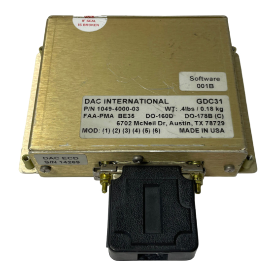
Equipment Installation Manual, GDC31 Roll Steering Converter SPECIFICATIONS: Physical: The GDC31 attaches to the airframe via four mounting holes. See the paragraph titled GDC31 Outline Drawing for further details. RSC LRU Height..........1.25” Width..........5.22” (Includes mounting flange) Depth..........3.54” Weight..........0.4 lb. The Isolation Coupler (optional) attaches to the airframe via four mounting holes. See the paragraph titled Isolation Coupler Outline Drawing for further details. -
Page 10: Serial Data Input
Reference Inputs: General Description ......AC or DC excitation used to excite the heading bug on the HSI or DG. The GDC31 uses the reference input to produce a steering signal with correct phase and amplitude characteristics. Two reference inputs are provided. Use only one, depending on the autopilot type. -
Page 11: Ap Offset Input
GPS Coupled........Normally Open relay contacts configured as a SPST switch intended to control an external GPS mode annunciator. The GDC31 closes the contacts when the steering output is valid. It cycles the contacts between open and closed at a 1 Hz rate if steering data is invalid. -
Page 12: Operation
(refer to Tables 1, 2 and 3). The GDC31 will accept either an AC or a DC reference input as well as reference inputs that contain an offset from airframe ground. The internal circuitry implements a multiplying Digital-to- Analog converter that uses the external reference input to produce the desired signal output amplitude and phase relative to the reference input. -
Page 13: Gps Mode Annunciator Control
Super Flag Input The GDC31 reads the Super Flag (14 or 28Vdc) from the GPS receiver. If the flag is greater than 5Vdc, the flag shall be considered valid, if less than 2Vdc, the flag shall be considered as invalid. If the Super... -
Page 14: Installation
Equipment Installation Manual, GDC31 Roll Steering Converter INSTALLATION This section provides details for the installation of the GDC31 Roll Steering Converter, including configuration, wiring, mounting and checkout procedures. Follow the procedures and recommendations found in this section to assure a successful installation. -
Page 15: Mounting Considerations
GDC31 Roll Steering Converter Mounting Considerations The GDC31 Roll Steering Converter can mount in the avionics bay, shelf or other suitable structure. It can be mounted in any orientation. The optional Isolation Coupler can mount in the avionics bay, shelf or other suitable structure. It can be mounted in any orientation. -
Page 16: Steering Output Scale Factor Determination
Steering Output Scale Factor Determination The GDC31 is designed to mimic the heading error signal produced by the existing HSI or DG, so it can operate with the wide variety of autopilots in current use. These various autopilots employ a wide range of reference voltages and scale factors to interface with the array of HSI and DG control heads. -
Page 17: Configuration Pins
GDC31 Roll Steering Converter Configuration Pins The GDC31 produces one of four (4) different RSS output levels for each reference input. This scaling selection is accomplished with program pins J1-10 and J1-22. Tables 1 and 2 define the scale factors... -
Page 18: Phase Selection
GDC31 Roll Steering Converter Phase Selection The GDC31 will accommodate steering signals that are in phase with the reference or out of phase with the reference. For DC heading error signals, in-phase means a positive error signal produces a right turn, a negative error signal produces a left turn. -
Page 19: Position/Rate Selection
Determine the autopilot type, if it is rate based then connect J1-23 to program pin common, J1-11. Baud Rate Selection The GDC31 will accept four (4) baud rates for GPS data configured using program pins P1-9 and P1-21. Baud Rate P1-9... -
Page 20: Removal And Replacement
GDC31 Roll Steering Converter REMOVAL AND REPLACEMENT Removal, GDC31 1. Open the circuit breaker powering the GDC31. 2. Remove the connector by disengaging the slide latch then pulling the connector free. 3. Remove four (4) screws securing the unit to the airframe. -
Page 21: Equipment Checkout
GDC31 Roll Steering Converter EQUIPMENT CHECKOUT The GDC31 provides conversion of Serial data from a GPS receiver into a steering signal connected to the autopilot heading channel through switching controlled by the HDG/GPS mode selector switch. There are no other operator controls associated with the GDC31 unit. - Page 22 7. Place the HDG/GPS Mode selector in the GPS position. Observe that GPS illuminates and is not blinking. 8. Observe that the aircraft turns to intercept the course selected in Step 6. Note: The GDC31 limits the intercept angle to 45º maximum. (Intercept angle = difference between Desired Track and Track.)
-
Page 23: Continued Airworthiness
Application of Protective Treatments ............ None Required Special Tools..................None Required Electrical Loads for this appliance are as specified in the DAC International Installation Manual, 1049-2510-01 (this manual). There are no Airworthiness limitations associated with the installation of this appliance. -
Page 24: Environmental
Equipment Installation Manual, GDC31 Roll Steering Converter ENVIRONMENTAL: The GDC31 meets the environmental test categories detailed below in accordance with RTCA/DO-160D, Environmental Conditions and Test Procedures for Airborne Equipment. NOMENCLATURE: Model GDC31 Roll Steering Converter PART NO: 1049-4000-XX-XXXX MANUFACTURER: DAC International... -
Page 25: Connector Pin Out
Equipment Installation Manual, GDC31 Roll Steering Converter CONNECTOR PIN OUT: The GDC31 contains a single 25-pin male connector, J1, per MIL-C-24308. The mating connector, P1, is described previously under the section “Equipment Supplied”. Signal Function 28 Vdc Primary Power Serial Out... -
Page 26: Outline Drawings
Equipment Installation Manual, GDC31 Roll Steering Converter OUTLINE DRAWINGS GDC31 Outline Note: Dimensions are in inches. 1049-2510-01 1049-2510-01 G.doc Rev G Page 26 of 47... -
Page 27: Switch / Annunciator Outline
Equipment Installation Manual, GDC31 Roll Steering Converter Switch / Annunciator Outline PIN OUT (REAR VIEW) PANEL CUTOUT Outline for part number P10280 Note: Dimensions are in inches. 1049-2510-01 1049-2510-01 G.doc Rev G Page 27 of 47... -
Page 28: Isolation Coupler Outline
Equipment Installation Manual, GDC31 Roll Steering Converter Isolation Coupler Outline 1049-2510-01 1049-2510-01 G.doc Rev G Page 28 of 47... -
Page 29: Slide Latch Assembly
Equipment Installation Manual, GDC31 Roll Steering Converter SLIDE LATCH ASSEMBLY Assemble the slide latch mechanism, part number P10219 or P10053, onto the mating connector as pictured using the hardware supplied with the slide latch. LOCK WASHER FLAT WASHER CONNECTOR SLIDE LATCH... -
Page 30: Appendix A - Aviation Format
GPS. The preferred baud rate is 9600 baud, however, the GDC31 will accept 2400, 4800 or 19200 baud. Insure the GDC31 is configured for the correct baud rate (refer to "Serial Baud Rate Selection" located earlier in... -
Page 31: Appendix B - 429 Output
Equipment Installation Manual, GDC31 Roll Steering Converter APPENDIX B – 429 OUTPUT Label 121 - Bank Angle Command Label 121 shall be formatted as follows: Roll Angle (two’s compliment if negative) Label 121 P = odd parity SSM = sign status matrix... -
Page 32: Appendix C - Typical Interconnect
GDC31 Roll Steering Converter APPENDIX C - TYPICAL INTERCONNECT The following section contains typical interconnect diagrams to aid in wiring the GDC31. All wiring, wire gauge and wire type shall be according to the INSTALLATION section of this manual. Mounting shall use the hardware called out in this manual or AN / MS equivalent fasteners. -
Page 33: Figure 1 Typical Interconnect
SUPER FLAG IN SUPER FLAG OUT ISOLATION COUPLER IS USED TO TRANSFORMER ISOLATE THE BAUD SELECT 0 GDC31 REFERENCE AND / OR OUTPUT FOR INSTALLATIONS WHERE BAUD SELECT 1 THESE SIGNALS ARE NOT REFERENCED TO AIRFRAME GROUND. GAIN SELECT 0... - Page 34 Equipment Installation Manual, GDC31 Roll Steering Converter BENDIX/KING SWITCH / ANNUN RSS CONVERTER BENDIX/KING BENDIX/KING KI 525 / 525A P10280 GDC31 KA 57 KA 52 +15V -15V SIGNAL GROUND TO AUTOPILOT / RADIO COUPLER HDG/CRS RETURN HEADING ERROR AP Out...
-
Page 35: Figure 3 Arinc Hsi With Century Iv
Equipment Installation Manual, GDC31 Roll Steering Converter COLLINS KING WILCOX SPERRY SWITCH / ANNUN RSS CONVERTER CENTURY IV PN 101 KPI-550 1041A RD-444-447 P10280 GDC31 ID496 COMPUTER P201 5KHz EXCITATION SIGNAL GROUND HEADING ERROR AP Out Ref 1 Lamp A... -
Page 36: Figure 4 Arinc Hsi With S-Tec 50, 55 Or 60
Equipment Installation Manual, Equipment Installation Manual, GDC31 Roll Steering Converter GDC31 Roll Steering Converter COLLINS COLLINS KING KING WILCOX WILCOX SPERRY SPERRY SWITCH / ANNUN SWITCH / ANNUN RSS CONVERTER RSS CONVERTER S-TEC S-TEC S-TEC S-TEC S-TEC S-TEC PN 101... -
Page 37: Figure 5 Nsd 360A / Nsd 1000 With Century Iv
Equipment Installation Manual, GDC31 Roll Steering Converter NSD 360A SWITCH / ANNUN RSS CONVERTER CENTURY IV NSD 1000 P10280 GDC31 ID496 +14V -14V COMMON HEADING ERROR AP Out Ref 2 Lamp A Lamp B AP Com Offset Prog Com Gain Sel 0... -
Page 38: Figure 6 Nsd 360A / Nsd 1000 With S-Tec 50 Or 55
Equipment Installation Manual, GDC31 Roll Steering Converter NSD 360A SWITCH / ANNUN RSS CONVERTER S-TEC S-TEC S-TEC NSD 1000 P10280 GDC31 Ref 2 +10VDC EXCITATION AP Com EXCITATION GND HEADING ERROR AP Out Lamp A Lamp B Offset SIGNAL REF... -
Page 39: Figure 7 Arinc Hsi With Century Ii Or Iii
Equipment Installation Manual, GDC31 Roll Steering Converter COLLINS KING WILCOX SPERRY SWITCH / ANNUN RSS CONVERTER ISOLATION CENTURY CENTURY PN 101 KPI-550 1041A RD-444-447 P10280 GDC31 COUPLER IC388-3 IC388-MC 1049-4801-01 CD 33 PIGTAIL CD 33 PIGTAIL P201 ROLL EXCITATION ROLL EXCITATION... -
Page 40: Figure 8 Ki 525A With Kfc 150
Equipment Installation Manual, GDC31 Roll Steering Converter KFC-150 KC-19(X) FLIGHT SWITCH / ANNUNC COMPUTER KI 525A SWITCH / ANNUNC RSS CONVERTER P10280 P10280 GDC31 P19(X)1 P19(X)2 SCHEMATIC +15VDC +15 VDC REG -15VDC -15 VDC REG HDG/CRS REF DATUM REF HDG DATUM... -
Page 41: Figure 9 Nsd 360 With Arc 400B (10Vac)
Equipment Installation Manual, GDC31 Roll Steering Converter SPERRY/ARC-400B SWITCH / ANNUNC CA-550A/FD P10280 10VAC HEADING SCHEMATIC NSD-360A DATUM NSD-1000 SWITCH / ANNUNC RSS CONVERTER IG-832 A/C P10280 GDC31 J1/P4 J2/P5 10VAC 400HZ 400HZ RTN AC HDG IN HDG SIGNAL CHASSIS GND... -
Page 42: Figure 10 52D54 Dg With Stec 50, 55 Or 60
Equipment Installation Manual, GDC31 Roll Steering Converter ISOLATION 52D54 SWITCH / ANNUN RSS CONVERTER S-TEC S-TEC S-TEC COUPLER P10280 1049-4801-01 GDC31 EXCITATION EXCITATION SIG REF SIG REF HDG ERROR HDG ERROR AP Out Ref 1 Lamp A 24 Lamp B... -
Page 43: Figure 11 Nsd 360 With Arc 400B (Dc)
Equipment Installation Manual, GDC31 Roll Steering Converter SPERRY/ARC-400B CA-550A/FD SWITCH / ANNUNC DC HEADING NSD-360A P10280 DATUM NSD-1000 SWITCH / ANNUNC RSS CONVERTER SCHEMATIC IG-832 A/C P10280 GDC31 J1/P4 -10VDC REG +10VDC REG DC HDG IN HDG SIGNAL SIGNAL GND... -
Page 44: Figure 12 Nsd 360 With Century 2000
Equipment Installation Manual, GDC31 Roll Steering Converter NSD-360A CENTURY 2000 NSD-1000 SWITCH / ANNUNC RSS CONVERTER CD175 CD220 IG-832 A/C P10280 GDC31 HDG CRS DC EXC (REG V+) HDG CRS DC EXC GND DC HEADING SIGNAL HDG SIGNAL 21 AP-OUT... -
Page 45: Figure 13 Nsd 360A With Century Ii Or Iii
Equipment Installation Manual, GDC31 Roll Steering Converter NSD-360A NSD-1000 IU445-004-11 SWITCH / ANNUN RSS CONVERTER ISOLATION CENTURY CENTURY IU445-003-17 P10280 GDC31 COUPLER IC388-2 IC388-2 1049-4801-01 CD 33 PIGTAIL CD 33 ROLL EXCITATION ROLL EXCITATION HEADING ERROR HDG SIGNAL HEADING ERROR... -
Page 46: Figure 14 Hsi-70C With Arc 1000
Equipment Installation Manual, GDC31 Roll Steering Converter ISOLATION HSI-70C SWITCH / ANNUN COUPLER RSS CONVERTER ARC 1000 P10280 GDC31 1049-4801-01 26VAC 400HZ AC HDG SIG AP Out Ref 1 Lamp A 24 Lamp B AC HDG COM LIGHTING BUS 14 OR 28VDC... -
Page 47: Figure 15 Ki 525A With Kfc 200 / 300
Equipment Installation Manual, GDC31 Roll Steering Converter KI 525A SWITCH / ANNUNC RSS CONVERTER KFC-200 / KFC-300 P10280 GDC31 COMPUTER +15VDC +15 VDC REG -15VDC -15 VDC REG SIGNAL GND SIGNAL GND KG-102A HDG/CRS REF DATUM REF DIRECTIONAL GYRO HDG DATUM...
Need help?
Do you have a question about the GDC31 and is the answer not in the manual?
Questions and answers