Table of Contents
Advertisement
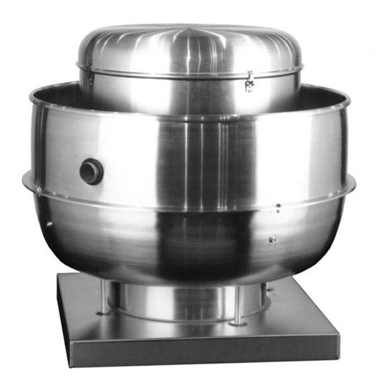
This publication contains the installation, operation
and maintenance procedures for standard units of the
VCR/VCRD/VCR-HP/VCRD-HP/VCR-XP/VCRD-XP
Centrifugal Roof and Wall Exhausters. Carefully read
this publication prior to installation or maintenance
procedure.
Loren Cook catalog, VCR, provides additional informa-
tion describing the equipment, fan performance, available
accessories and specification data.
For additional safety information, refer to AMCA publica-
tion 410-96, Safety Practices for Users and Installers of
Industrial and Commercial Fans.
All of the publications listed above can be obtained from
Loren Cook Company by phoning (417)869-6474, exten-
sion 166; by FAX at (417)832-9431; or by e-mail at
info@lorencook.com.
For information and instructions on special equipment,
contact Loren Cook Company at (417)869-6474.
Receiving and Inspection
Immediately upon receipt of a VCR fan, carefully inspect
the fan and accessories for damage and shortage.
• Turn the wheel by hand to ensure it turns freely and
does not bind.
• Record on the Delivery
Receipt any visible sign of
damage.
Handling
Lift the fan by the lifting lugs
provided under top cap. Never lift
by the shaft, motor or housing.
Storage
If the fan is stored for any
length of time prior to installation,
store it in its original shipping
crate and protect it from dust,
debris and the weather.
WARNING
This fan has rotating parts. Safety precautions
should be exercised at all times during installation,
operation, and maintenance.
ALWAYS disconnect power prior to working on fan.
Installation
If the fan was delivered with the motor unmounted, see
the maintenance sections for belt and pulley installation.
If the fan was purchased as a wall mount unit and a
grease terminator or grease trough was not purchased, a
INSTALLATION, OPERATION, AND MAINTENANCE MANUAL
Lifting Lugs
Centrifugal Roof and Wall Exhausters
1-1/16 inch diameter drain hole should be inserted on the
bottom side of the unit for drainage.
-
Personal Safety
Disconnect switches are recommended. Place
the disconnect switch near the fan in order that
the power can be swiftly cut off in case of an
emergency, and in order that maintenance per-
sonnel are provided complete control of the
power source.
Fan Installation
a. Ensure the fan discharge is a minimum 40 inches
above the roof surface and a minimum of 10 foot from
any building air intake in order to comply with NFPA 96.
b. Minimum exhaust velocity in the duct should be 1500
FPM in accordance with NFPA 96.
c. If the fan is installed on a surface that is not level, install
the fan in a position that places the drain tube at the
lowest position.
d. Secure the fan to the roof curb at all four corners using
a minimum of four anchor bolts, lag screws or other
suitable fastener.
VCR / VCRD
VCR
Advertisement
Table of Contents

Summary of Contents for COOK VCR
- Page 1 Secure the fan to the roof curb at all four corners using Receiving and Inspection a minimum of four anchor bolts, lag screws or other Immediately upon receipt of a VCR fan, carefully inspect suitable fastener. the fan and accessories for damage and shortage.
-
Page 2: Final Installation Steps
Terminator capacity of wires) is in accordance with the motor name- plate. Refer to the Wiring Diagrams, next page. VCR with Terminator Do not use cooling tubes for electrical connections. Upblast units have two wiring conduits. Upblast units have two wiring conduits. The vertical conduit comes plugged. -
Page 3: Wiring Diagrams
FAN* If a problem is discovered, immediately shut the fan off. Lock out all electrical power and check for the *See VCR Wiring Diagram for correct lead. cause of the trouble. Refer to Troubleshooting, page 6. † Locate away from heat. -
Page 4: Maintenance
Removing dust and grease on motor housing assures Should the motor prove defective within a one-year period, proper motor cooling. contact your local Loren Cook representative or your nearest Grease Terminator authorized electric motor service representative. Regular inspections of the Grease Terminator 2 are rec- Changing Shaft Speed ommended. -
Page 5: Replacing Pulleys And Belts
Loosen the motor plate mounting bolts to relieve the belt tension. Remove the belt. c. Loosen the pulley setscrews and remove the pulleys from the shaft. Maximum RPM Maximum RPM Maximum RPM VCR-HP Size Size Standard Reinforced Standard Reinforced 2002 1952... -
Page 6: Wheel Replacement
d. Correctly position the wheel and tighten the bearing cone and the edge of the inlet) is obtained by loosening the bolts securely to the bearing support. inlet cone bolts and repositioning the inlet cone. e. Align setscrews bearing to bearing and secure tightly to the shaft. -
Page 7: Parts List
Parts List VCR/VCR-HP/VCR-XP Parts Description Part 100-225 270-490 Top Cap Lid Top Cap Lid Top Cap Lid VCR/VCR-HP/VCR-XP Parts Top Cap Cylinder Top Cap Cylinder Top Cap Cylinder Top Cap Clip (4) Top Cap Clip (4) Top Cap Clip (8) - Page 8 Dale Street, Springfield, Missouri 65803-4637, explaining in writing, in detail, your complaint and referring to the specific model and serial numbers of your fan. Upon receipt by Loren Cook Company of your written complaint, you will be notified, within thirty (30) days of our receipt of your complaint, in writing, as to the manner in which your claim will be handled.
Need help?
Do you have a question about the VCR and is the answer not in the manual?
Questions and answers