Table of Contents
Advertisement
Available languages
Available languages
Quick Links
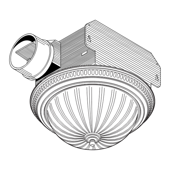
DECORATIVE SERIES
CEILING VENTILATOR
READ AND SAVE THESE INSTRUCTIONS
WARNING
TO REDUCE THE RISK OF FIRE, ELECTRIC
SHOCK, OR INJURY TO PERSONS, OBSERVE
THE FOLLOWING:
1. Use this unit only in the manner intended
by the manufacturer. If you have questions,
contact the manufacturer at the address or
telephone number listed in the warranty.
2. Before servicing or cleaning unit, switch
power off at service panel and lock the ser-
vice disconnecting means to prevent power
from being switched on accidentally. When
the service disconnecting means cannot be
locked, securely fasten a prominent warning
device, such as a tag, to the service panel.
3. Installation work and electrical wiring must be
done by a qualified person(s) in accordance
with all applicable codes and standards,
including fire-rated construction codes and
standards.
4. Sufficient air is needed for proper combus-
tion and exhausting of gases through the flue
(chimney) of fuel burning equipment to prevent
backdrafting. Follow the heating equipment
manufacturer's guideline and safety standards
such as those published by the National Fire
Protection Association (NFPA), and the Ameri-
can Society for Heating, Refrigeration and Air
Conditioning Engineers (ASHRAE), and the
local code authorities.
5. When cutting or drilling into wall or ceiling, do
not damage electrical wiring and other hidden
utilities.
6. Ducted fans must always be vented to the
outdoors.
7. NEVER place a switch where it can be
reached from a tub or shower.
8. This unit must be grounded.
9. This unit is U.L. listed. Type I.C. inherently
protected.
!
CAUTION
1. For general ventilating use only. Do not use
to exhaust hazardous or explosive materials
and vapors.
2. This product is designed for ceiling installation
only. This product is designed for installation
in ceilings up to a 12/12 pitch. Ductwork must
point up. DO NOT MOUNT THIS PRODUCT
IN A WALL.
3. The light fixture assembly must be mounted
to the fan housing assembly included with
this product. Do not mount the light fixture
assembly to a wiring outlet box.
4. To avoid motor bearing damage and noisy
and/or unbalanced impellers, keep drywall
spray, construction dust, etc. off power unit.
5. Please read specification label on product for
further information and requirements.
TYPICAL INSTALLATIONS
POWER CABLE
MOUNTING TABS
CEILING
JOIST
HOUSING
CEILING
MATERIAL
LIGHT SHADE
HOUSING MOUNTED
DIRECTLY TO JOIST
2x6 (or larger)
Discharge parallel to joists.
POWER CABLE
ADDITIONAL
MOUNTING
TABS
2 x 4
CEILING
JOIST or
TRUSS
HOUSING
CEILING
MATERIAL
LIGHT SHADE
HOUSING MOUNTED
TO 2x4 TRUSS
Requires additional framing
for mounting tabs.
Discharge parallel to joists.
ADDITIONAL
POWER CABLE
FRAMING
MOUNTING
TABS
HOUSING
I
"
"
JOIST
CEILING
MATERIAL
GRILLE
GLASS LIGHT SHADE
PAN
HOUSING MOUNTED TO "I" JOIST
Requires additional framing
for mounting tabs.
Discharge parallel to joists.
*
Additional framing must be a 2x6 (minimum height).
Installer: Leave this manual with the homeowner.
Homeowner: Use and Care information on page 4.
GRILLE
CEILING
PAN
MATERIAL
GLASS
GLASS
LIGHT SHADE
HOUSING MOUNTED
TO ADDITIONAL FRAMING
Discharge 90
*
FRAMING
2 x 4
CEILING
JOIST or
TRUSS
GRILLE
2 x 4
PAN
CEILING
GLASS
JOIST or
TRUSS
GLASS
LIGHT SHADE
HOUSING MOUNTED TO 2x4
Requires additional framing
Discharge 90
*
POWER CABLE
I
"
"
I
"
"
JOIST
JOIST
GLASS
LIGHT SHADE
HOUSING MOUNTED TO "I" JOIST
Requires additional framing
Discharge 90
MODEL 741SN
Page 1
4" ROUND
DUCT
POWER CABLE
MOUNTING TABS
HOUSING
ADDITIONAL
FRAMING
GRILLE PAN
to joists.
0
4" ROUND
DUCT
POWER CABLE
MOUNTING TABS
HOUSING
ADDITIONAL
FRAMING
CEILING
MATERIAL
GRILLE PAN
TRUSS
for mounting tabs.
to joists.
0
4" ROUND
DUCT
MOUNTING TABS
HOUSING
ADDITIONAL
*
FRAMING
GRILLE
CEILING
PAN
MATERIAL
for mounting tabs.
to joists.
0
*
CEILING
JOIST
*
2 x 4
CEILING
JOIST or
TRUSS
I
"
"
JOIST
Advertisement
Table of Contents

Related Manuals for Broan 741SN


Summary of Contents for Broan 741SN
-
Page 1: Typical Installations
MODEL 741SN Page 1 DECORATIVE SERIES CEILING VENTILATOR READ AND SAVE THESE INSTRUCTIONS WARNING TYPICAL INSTALLATIONS TO REDUCE THE RISK OF FIRE, ELECTRIC SHOCK, OR INJURY TO PERSONS, OBSERVE 4" ROUND DUCT THE FOLLOWING: POWER CABLE POWER CABLE 1. Use this unit only in the manner intended... -
Page 2: Existing Construction
MODEL 741SN Page 2 TYPICAL INSTALLATIONS INSTALL THE HOUSING (continued) (continued) New Construction 4" ROUND DUCT POWER CABLE MOUNTING HOUSING GRILLE SUSPENDED CEILING GLASS MATERIAL LIGHT SHADE SUSPENDED CEILINGS Housing hung with wires - 3-point mount. INSTALL THE HOUSING 3. Set housing aside and drive nails partially into joist at the top of both keyhole marks. -
Page 3: Connect The Wiring
MODEL 741SN Page 3 INSTALL THE HOUSING 2. Connect 4” round duct to damper/duct connector and (continued) extend duct to outside through a roof or wall cap. Check damper to make sure that it opens freely. Tape all duct connections to make them secure and air tight. -
Page 4: Service Parts
Order replacement parts by “PART NO.” - not by “KEY NO.” During this one-year period, Broan-NuTone will, at its option, repair or replace, without charge, any product or part which is found to be defective under normal use and service. -
Page 5: Instalaciones Típicas
MODELO 741SN Page 5 Página 5 VENTILADORE DE CIELO RASO SERIE DECORATIVA LEA Y CONSERVE ESTAS INSTRUCCIONES ADVERTENCIA INSTALACIONES TÍPICAS PARA REDUCIR EL RIESGO DE INCENDIO, DESCARGA CABLE DE ALIMENTACIÓN CONDUCTO ELÉCTRICA O LESIONES PERSONALES, OBSERVE LO REDONDO DE CABLE... -
Page 6: Instalación De La Cubierta
MODELO 741SN Page 6 Página 6 INSTALACIÓN DE LA INSTALACIONES TÍPICAS CUBIERTA (continuación) (continuación) Construcción nueva CONDUCTO REDONDO DE 4" (10.2 cm) CABLE DE ALIMENTACIÓN ALETA DE CUBIERTA MONTAJE PLATILLO MATERIAL DE REJILLA DEL TECHO PANTALLA SUSPENDIDO DE VIDRIO TECHOS SUSPENDIDOS Cubierta montada con cables. -
Page 7: Conexión Eléctrica
MODELO 741SN Page 7 Página 7 INSTALACIÓN DE LA 2. Conecte el conducto redondo de 4” (10.2 cm) en el conector del CUBIERTA (continuación) regulador de tiro/conducto y extienda el conducto hasta el exterior a través de una tapa de techo o de pared. Revise el regulador Construcción existente... -
Page 8: Uso Y Cuidado
OTRAS GARANTIAS EXPLICITAS O IMPLICITAS, INCLUYENDO, PERO NO LIMITADAS A GARANTIAS IMPLICITAS DE COMERCIALIZACION O APTITUD PARA UN PROPOSITO PARTICULAR. Durante este período de un año, Broan-NuTone reparará o cambiará, a su opción y sin cobro, cualquier producto o Encargue piezas de servicio por “N PIEZA”...
Need help?
Do you have a question about the 741SN and is the answer not in the manual?
Questions and answers
Can I replace the fan motor and blades on 741SN product
Yes, the fan motor on the Broan 741SN can be replaced. The context mentions a user successfully replacing the motor with a direct replacement that fit perfectly. While the blades are not specifically mentioned, fan motors for this type of unit typically include the blade attached, so replacing the motor usually replaces the blades as well.
This answer is automatically generated