Table of Contents
Advertisement
Quick Links
g
GE Multilin
215 Anderson Avenue
L6E 1B3 Markham, ON -CANADA
Tel: (905) 294 6222 Fax: (905) 294 8512
E-mail: gemultilin@ge.com
Internet: www.GEMultilin.com
GE Consumer & Industrial
Multilin
DTP-B
Digital Transformer Protection
Instruction manual
GEK-106243E
Copyright © 2005 GE Multilin
GE Multilin
Avda. Pinoa, 10
48170 Zamudio SPAIN
Tel: +34 94 485 88 00 Fax: +34 94 485 88 45
E-mail: gemultilin.euro@ge.com
Advertisement
Table of Contents

Subscribe to Our Youtube Channel
Summary of Contents for GE Multilin DTP-B
- Page 1 GE Consumer & Industrial Multilin DTP-B Digital Transformer Protection Instruction manual GEK-106243E Copyright © 2005 GE Multilin GE Multilin GE Multilin Avda. Pinoa, 10 215 Anderson Avenue 48170 Zamudio SPAIN L6E 1B3 Markham, ON -CANADA Tel: +34 94 485 88 00 Fax: +34 94 485 88 45 Tel: (905) 294 6222 Fax: (905) 294 8512 E-mail: gemultilin.euro@ge.com...
-
Page 2: Table Of Contents
TABLE OF CONTENTS 1. GENERAL DESCRIPTION 2. APPLICATION DESCRIPTION CALCULATIONS 2.2.1 METHOD 2.2.2 PHASE SHIFT COMPENSATION 2.2.3 CALCULATION OF CT TRANSFORMATION RATIOS AND RELAY TAPS 2.2.4 PERCENTAGE RESTRAINT SETTING TRANSFORMER CALCULATIONS (FIGURE 6) 2.3.1 1 ITERATION. CALCULATIONS REFERRED TO THE TRANSFORMER SHOWN IN FIGURE 6 2.3.2 2 ITERATION. - Page 3 INSULATION TESTS POWER SUPPLY MEASUREMENT CHECK DIGITAL INPUTS CHECKING OUTPUTS CHECKING 9.7.1 TRIP OUTPUTS CHECKING. 9.7.2 ALARM OUTPUTS CHECKING. 9.7.3 CONFIGURABLE OUTPUTS CHECKING. COMMUNICATION PORTS CHECKING KEYPAD, DISPLAY, AND LEDS CHECKING. 9.10 OPERATIONS 9.10.1 TIME SETTING. DTP-B Digital Transformer Protection GEK-106243E...
- Page 4 TABLE OF CONTENTS 9.10.2 COMMUNICATIONS TRIGGER. 9.11 PERCENTAGE RESTRAINT CHECKING 9.12 HARMONIC RESTRAINT CHECKING 9.13 INSTANTANEOUS FUNCTION CHECKING 10. INSTALLATION AND MAINTENANCE 10-1 10.1 INSTALLATION 10-1 10.2 CONNECTION TO GROUND AND SUPPRESSION OF DISTURBANCES 10-1 10.3 MAINTENANCE 10-1 11. KEYBOARD AND DISPLAY 11-1 11.1 MENU TREE 11-2...
- Page 5 Fig. 4: Dimensions diagram Fig. 5: Front view Fig. 6: Sample transformer for the calculation of settings Fig. 7: Operating principles of the differential protection Fig. 8: Block diagram of the protection Fig. 9: Percentage Characteristic DTP-B Digital Transformer Protection GEK-106243E...
-
Page 6: General Description
1. GENERAL DESCRIPTION 1. GENERAL DESCRIPTION During the last years, new technologies have achieved an important improvement in the concept of function integration between the different components of electrical systems. There are several reasons for that integration: • Reduce the investment in new equipment. •... - Page 7 • GE-INTRO Configuration Software, used for the configuration of inputs, outputs, alarms and LED indicators. • GE-OSC Oscillography Software, for monitoring and analyzing oscillography records. These software packages are part of GE-NESIS (General Electric NEtwork Substation Integrated System) DTP-B Digital Transformer Protection GEK-106243E...
-
Page 8: Application
2. APPLICATION 2. APPLICATION 2.1 DESCRIPTION The current transformer ratios and relay taps must be selected to obtain the maximum sensitivity without risking relay measurement overflow, thermal overload of the relay or current transformers. Due to the low level of load presented by the relay, which has a permanent thermal capacity of 4 times In, and a transient capacity of 100 x In, it is very improbable to cause an overload this way. - Page 9 Should one DTP relay be used to protect two independently switched parallel transformers, the DTP relay’s harmonic restraint (adjustable from 12% to 50%) may be increased to preclude a misoperation. DTP-B Digital Transformer Protection GEK-106243E...
-
Page 10: Calculations
2. APPLICATION 2.2 CALCULATIONS 2.2.1 METHOD The calculations required to determine the proper relay taps and CT ratios are described below. A sample calculation, for the transformer shown in Figure 6, is presented. 2.2.2 PHASE SHIFT COMPENSATION The secondary currents applied to the relay must be in phase if the EXTERNAL COMPENSATION mode is used. The differential and through currents are obtained directly from the relay input currents, and any required phase shift compensation or zero-sequence current elimination must be obtained by proper connection (i.e., either wye or delta) of the current transformers. - Page 11 From the excitation curve of the CT that is being used, determine the excitation current (Ie) which corresponds to the voltage Esec. • Determine the percent error in each CT through the following expression: % error = ⎯⎯⎯⎯ x 100 DTP-B Digital Transformer Protection GEK-106243E...
-
Page 12: Percentage Restraint Setting
2. APPLICATION This value must not exceed 20% for any set of CTs. If it does, it will be necessary to choose a higher CT ratio and repeat the calculations for selecting the relay tap, mismatch error, and CT ratio error. Please refer to the example shown in section 2.3. -
Page 13: Transformer Calculations (Figure 6)
Relay current in selected winding 9. Ideal relay taps (select A= 2.5): 5.03 5.03 Select the closest available tap to the ideal taps 10. Actual relay taps (In=5) (0.5xIn) (1.0xIn) (1.0xIn) DTP-B Digital Transformer Protection GEK-106243E... - Page 14 2. APPLICATION 11. Check the mismatch error: 5.00/2.5 1.75/0.87 Windings A-B: ⎯⎯⎯⎯⎯⎯⎯⎯⎯⎯⎯⎯⎯ = -0.005% 5.00/2.5 5.00/5.00 1.75/1.75 Windings B-C: ⎯⎯⎯⎯⎯⎯⎯⎯⎯⎯⎯⎯⎯ = 0.000% 5.00/2.5 5.00/2.5 1.75/0.87 Windings C-A: ⎯⎯⎯⎯⎯⎯⎯⎯⎯⎯⎯⎯⎯ = -0.005% 5.00/2.5 This check is O.K. since all of the mismatch errors are less than 5%. In case of obtaining a high error, the unbalance will always be covered by the percentage restraint setting, although it is not recommended to have errors over 20% (including the variation due to the possible tap changer of the transformer).
- Page 15 The excitation current in winding B is excessive; therefore a higher CT ratio must be selected. The CT ratio for winding B will be increased and the matching error and CT Ratio error will be checked again. DTP-B Digital Transformer Protection GEK-106243E...
-
Page 16: Nd Iteration. New Ct Ratios For Windings B And C
2. APPLICATION 2.3.2 2 ITERATION. NEW CT RATIOS FOR WINDINGS B AND C 2.3.2.1 Matching Error Transformer winding 1. 100% Ip 17.5 2. New CT ratio 3. 100% Isec 0.87 0.87 1.17 4. Relay currents for 100% Isec 0.87 0.87 1.17 5. -
Page 17: Ct Configuration Setting
2.3.4 PERCENTAGE RESTRAINT SETTING K (FIGURE 9) The percentage restraint setting K is implemented in DTP-B relays in order to deal with unbalances caused by saturated CTs due to high currents borne during external faults. The break point between both slopes K... -
Page 18: Operating Principles
3. OPERATING PRINCIPLES 3. OPERATING PRINCIPLES 3.1 DESCRIPTION OF THE GENERAL OPERATING PRINCIPLE The basic principle of current differential protection is illustrated in Figure 7. When equal currents exist on both sides of the protected element in the directions indicated by Figure 7, as in the case of an external fault, no operate current will flow in the relay. -
Page 19: Measurement Algorithms
(performed by the DFT). Note that the instantaneous trip function uses the fundamental component of the differential current. This avoids undesired trips in certain situations and provides a high level of reliability and selectivity if the instantaneous trip level is properly adjusted. DTP-B Digital Transformer Protection GEK-106243E... -
Page 20: Through Current
3. OPERATING PRINCIPLES 3.2.2 THROUGH CURRENT Through current is defined as the smallest of the restraint currents for a through current condition (i.e., load flow or an external fault). This can be understood intuitively as the current that passes through the transformer. For an internal transformer fault where current flows in on each winding the through current is zero. -
Page 21: Internal States
Date/time alarm LED 8 Serial EEPROM alarm LED 9 Protection link LED 10 IRIG-B link LED 11 Events LED 12 LED 1 LED 13 LED 2 LED 14 LED 3 LED 15 LED 4 LED 16 DTP-B Digital Transformer Protection GEK-106243E... - Page 22 3. OPERATING PRINCIPLES The internal protection states are shown in the following table: TABLE II. INTERNAL PROTECTION STATES Internal State Internal State Internal State Program initiate Parallel E2PROM alarm AND1 Settings change Serial E2PROM alarm AND2 Configuration change Out of service AND3 External trigger Default general settings...
- Page 23 3. OPERATING PRINCIPLES DTP-B Digital Transformer Protection GEK-106243E...
-
Page 24: Functions Description
4. FUNCTIONS DESCRIPTION 4. FUNCTIONS DESCRIPTION 4.1 PROTECTION FUNCTIONS The DTP has two differential protection functions: • Function 87 with percentage restraint and harmonic restraint (second and fifth harmonic). • Programmable instantaneous protection (87B) for differential current. Their operation and application is described in sections 2 and 3. The percentage restraint characteristic is composed of two protection zones. -
Page 25: Self-Checking Functions
In addition there is a hardware test for the LED indicators, which light them all up when the button TARGET RESET is pressed. If the button is kept pressed down for more than one second the memory for all the indicators will be reset. DTP-B Digital Transformer Protection GEK-106243E... -
Page 26: Analysis Functions
4. FUNCTIONS DESCRIPTION 4.3 ANALYSIS FUNCTIONS 4.3.1 EVENT RECORDER The DTP equipment keeps a record of the last 166 events and stores the following information: date and time (1 msec. resolution), the type of event, the value of the differential and through currents measured at the time the event occurred, and the internal states matrix of the unit. -
Page 27: Settings Tables
NOTE: If the table control option is selected by these inputs, this selection will have priority over the “ACTIVE TABLE” setting, and the used table will be determined by the status of the digital inputs. DTP-B Digital Transformer Protection GEK-106243E... -
Page 28: Inputs And Outputs
4. FUNCTIONS DESCRIPTION 4.5 INPUTS AND OUTPUTS 4.5.1 DIGITAL INPUTS The DTP has 7 digital inputs (with a common), all of them configurable by the user with the GE_INTRO configuration software. One of the following values can be assigned to each input: •... -
Page 29: Human-Machine Interface (Mmi)
The unit can implement a different protocol, apart from MLINK. In this case, the relay communicates using MLINK by PORT1 (connectors 1 and 2), and the other protocol uses PORT2. DTP-B Digital Transformer Protection GEK-106243E... -
Page 30: Settings
5. SETTINGS 5. SETTINGS The following tables describe the settings incorporated in the DTP unit, together with their ranges, units and corresponding steps. The column marked DEFAULT indicates that this is the setting on the relay when it leaves the factory. It is possible to see the settings or to modify them manually, using the keyboard and display, or using a computer connected to any of the serial ports. - Page 31 Trip 87B A Enabled/ Disabled Enabled Trip 87B B Enabled/ Disabled Enabled Trip 87B C Enabled/ Disabled Enabled Trip 87 A Enabled/ Disabled Enabled Trip 87 B Enabled/ Disabled Enabled Trip 87 C Enabled/ Disabled Enabled DTP-B Digital Transformer Protection GEK-106243E...
- Page 32 5. SETTINGS Setting Limit Default Step Buchholz Trip Enabled/ Disabled Enabled Temperature Trip Enabled/ Disabled Enabled Input Trigger Enabled/ Disabled Enabled CommunicationTrigger Enabled/ Disabled Enabled Function Permission Group 87B Function permission Allowed/Not allowed Not allowed 87 Function permission Allowed/Not allowed Not allowed harmonic restraint Allowed/Not allowed...
- Page 33 The K1-K2 INFLEXION is the limit between two different zones of the percentage restraint. The set value is the through current value, for which the slope changes. The settings related to the third and fourth winding, will only be present in those units with 3 or 4 windings. DTP-B Digital Transformer Protection GEK-106243E...
-
Page 34: Unit Configuration
6. UNIT CONFIGURATION 6. UNIT CONFIGURATION The DTP protection system has user configurable inputs, outputs, and LED indicators. These configurations are performed using the GE_INTRO software. 6.1 INPUTS CONFIGURATION One of the following meanings can be assigned to any of the 7 inputs: •... -
Page 35: Outputs Configuration
For example, if we want LED12 to light up when the A differential function trips, we will follow these steps: • In the PROTECTION EVENT ASSIGNATION menu, we associate “Protection Event 1” to “Differential A Trip”. • In the LED assignation menu, we will associate LED12 to “Protection Event 1”. DTP-B Digital Transformer Protection GEK-106243E... -
Page 36: Technical Characteristics
7. TECHNICAL CHARACTERISTICS 7. TECHNICAL CHARACTERISTICS 7.1 MODEL LIST DESCRIPTION 2 Windings 3 Windings 4 Windings Comm. Protocols P1, P2, P3: Mlink P1, P2: Mlink ; P3: ModBus RTU In = 1A for all windings In = 5A for all windings In = 5A for winding 1 and In=1A for the rest of windings. -
Page 37: Technical Characteristics
30 x 10 - Mechanical Life • Burdens and Consumption: Ω - Current circuits: 0.03 , In = 5 A - Continuous: 12 W - Per active input: 8 mA (1 W Vaux = 125 Vcc) DTP-B Digital Transformer Protection GEK-106243E... -
Page 38: Communications
7. TECHNICAL CHARACTERISTICS 7.2.3 COMMUNICATIONS - RS232 using female DB9 connector (2/3 connectors depending on the model). - RS485 (depending on the model) - Mode: Half duplex. - 1 mm plastic Fiber Optic (depending on the model): Typical power output: -8 dBm Receiver sensitivity: -39 dBm... -
Page 39: Standards
Common mode • Electromagnetic fields radiated with ENV 50204 10 V/m frequency modulation • Fast transients IEC 255-22-4 EN 61000-4-4 • Magnetic fields at industrial frequency EN 61000-4-8 30 Av/m • RF emission EN 55011 DTP-B Digital Transformer Protection GEK-106243E... -
Page 40: Hardware Description
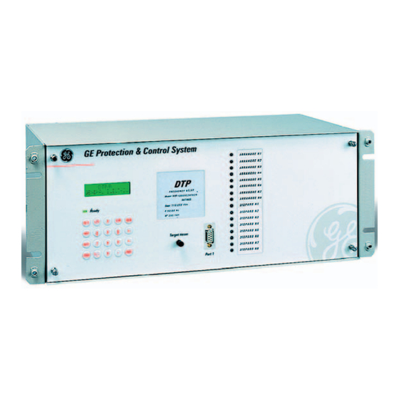
(IP52 index according to IEC 529). The use of a push-button allows access to the main functions without the need of removing the cover. The front view of a typical DTP-B equipment is shown on figure 5. 8.1.2 ELECTRICAL CONNECTIONS All the DTP electrical connections (voltage inputs and digital I/Os) are done through drawout terminal boards of 12 terminal blocks each, located on the rear of the device. -
Page 41: Internal Construction
2. Slack the fixed front screws until they are loose and fixed only by their fastening sleeve. 3. Let the front part fall steadily until the flat cable, that is connected to the communications port, is accessible, and disconnect it from this board. 4. Remove the front module. DTP-B Digital Transformer Protection GEK-106243E... -
Page 42: Identification
8. HARDWARE DESCRIPTION 5. Take out the internal bus board that holds the different modules. Following this process, every relay module can be accessed for taking it out, maintenance or replacements. In order to assemble the relay again, the opposite procedure should be followed, that is: 1. -
Page 43: Protection Cpu Processing Board
In every configuration, these are non potential contacts, without common elements, and all of them have varistors between their terminals in order to protect them against overvoltages generated by the coils to which they are connected. This provides a high immunity against electrical interferences. DTP-B Digital Transformer Protection GEK-106243E... -
Page 44: Power Supply
8. HARDWARE DESCRIPTION 8.1.9 POWER SUPPLY The Power Supply module includes the following functions: 1. Generation, from the external battery power supply, of the necessary voltages for electronic circuitry. In this case, 8 V (later regulated to 5 V) for the logic, and 24 V for the trips. 2. -
Page 45: Reception, Handling & Storage
DTP relays must be mounted on a vertical surface that allows access to the front and rear relay plates. It is not necessary to be able to access the side surfaces of the relay. Dimensions and panel drilling schemes are shown in figures 2 and 4. DTP-B Digital Transformer Protection GEK-106243E... -
Page 46: Acceptance Tests
9. ACCEPTANCE TESTS 9. ACCEPTANCE TESTS In this section, the necessary tests to check proper operation of the relay are described. The relay must have the factory configuration, so that the configurable inputs and outputs coincide with those indicated in the following tests. -
Page 47: Power Supply
If the unit sees both currents in counterphase Id = 0.00 and It = 1.00 Repeat the test with different values, and by the three phases, and check that the obtained values do not differ from the expected in more than a 5%. DTP-B Digital Transformer Protection GEK-106243E... -
Page 48: Digital Inputs Checking
9. ACCEPTANCE TESTS 9.6 DIGITAL INPUTS CHECKING For this test, the minimum and maximum admissible voltages will be applied to the inputs with a 20% rated voltage tolerance. Apply voltage to an input and check that the unit recognizes its activation by means of GE-LOCAL software. Repeat the test for the rest of inputs. -
Page 49: Communication Ports Checking
< CLR > DTP GENERAL ELECTRIC <7169> NET BAUD RATE < ↑> NET STOP BITS Now, dial all the numbers one by one, deleting them with the CLR key, and check that the pressed numbers are displayed. DTP-B Digital Transformer Protection GEK-106243E... -
Page 50: Operations
9. ACCEPTANCE TESTS 9.10 OPERATIONS 9.10.1 TIME SETTING. Set the date and time, and check that the setting is performed successfully. 9.10.2 COMMUNICATIONS TRIGGER. Apply a known current by any of the phases, and operate the communications trigger. Verify, retrieving the header of the last oscillography record by means of the GE-LOCAL software, that the retrieved time coincides with the correct time. -
Page 51: Instantaneous Function Checking
Apply current to the primary, and check that it trips when the differential current reaches the set value. Check that it trips with an error margin of less than 5% for different differential currents, and different instantaneous function settings. DTP-B Digital Transformer Protection GEK-106243E... -
Page 52: Installation And Maintenance
10. INSTALLATION AND MAINTENANCE 10. INSTALLATION AND MAINTENANCE 10.1 INSTALLATION The relay should be installed in a clean, dry and dust-free place, with no vibrations. It should also be well lit to facilitate inspection and testing. The relay should be mounted on a vertical surface. Figure 2 shows the diagram for panel drilling for panel mounting. - Page 53 10. INSTALLATION AND MAINTENANCE 10-2 DTP-B Digital Transformer Protection GEK-106243E...
-
Page 54: Keyboard And Display
11. KEYBOARD AND DISPLAY 11. KEYBOARD AND DISPLAY The DTP has a 20 key keyboard and a liquid crystal DISPLAY with 32 characters, divided into two rows of 16 each. The following diagram shows the appearance of the DTP keyboard: The keyboard program uses menus to access the different relay functions. -
Page 55: Menu Tree
• Shows the through current in phase B, in times the tap • THROUGH Ic • Shows the through current in phase C, in times the tap • PROTEC. STATUS • Shows the status of the protection system 11-2 DTP-B Digital Transformer Protection GEK-106243E... - Page 56 11. KEYBOARD AND DISPLAY Group Level 1 Description (in/out of service) • ACTIVE TABLE • Shows the active settings table # • DATE & TIME • Shows date and time of the unit • NET. BAUDRATE • Communication 7169 baud rate remote network...
-
Page 57: Settings Group
Change from winding current to .5 to 20 in steps CT current of 0.01 x In WINDING TAP Change from winding current to .5 to 20 in steps CT current of 0.01 x In 11-4 DTP-B Digital Transformer Protection GEK-106243E... - Page 58 11. KEYBOARD AND DISPLAY Level 1 Level 2 Level 3 Presentation Valid Range WINDING CONN Configuration of the first winding Y, D, ZZ WINDING Configuration of the second Y, D, ZZ CONN winding WDG H GROUP Time group of the second winding 0 to 11 WINDING Configuration of the third winding...
- Page 59 Percentage restraint of the second 15% - 100% slope HARM RESTR Second harmonic restraint 12% - 100% HARM RESTR Fifth harmonic restraint 12% - 100% 87B TAP Pickup value for the 87B unit 4 - 12 x It 11-6 DTP-B Digital Transformer Protection GEK-106243E...
- Page 60 11. KEYBOARD AND DISPLAY These are the steps to be taken in order to change any setting: 1. Press the SET key. 2. Select the option MODIFY SETTINGS. 3. Select the required setting in the menu trees. 4. ENTER the value to be modified (or select the required value from the list of available settings using LEFT/RIGHT ARROW keys).
-
Page 61: Information Group
Phase B differential current DIFFERENTIAL Ic Phase C differential current DIF Ia 2ND HARM Phase A 2 harmonic current DIF Ib 2ND HARM Phase B 2 harmonic current DIF Ic 2ND HARM Phase C 2 harmonic current 11-8 DTP-B Digital Transformer Protection GEK-106243E... - Page 62 11. KEYBOARD AND DISPLAY Status Description DIF Ia 5TH HARM Phase A 5 harmonic current DIF Ib 5TH HARM Phase B 5 harmonic current DIF Ic 5TH HARM Phase C 5 harmonic current THROUGH Ia Phase A through current THROUGH Ib Phase B through current THROUGH Ic Phase C through current...
-
Page 63: Operations Group
Using the GE_LOCAL communication software, it is possible to retrieve the last four oscillography records and save them in a COMTRADE ASCII format file. In order to view these files, the GE_OSC software is needed. 11-10 DTP-B Digital Transformer Protection GEK-106243E... -
Page 64: Single Key Operation
11. KEYBOARD AND DISPLAY 11.5 SINGLE KEY OPERATION The DTP has a simplified operation mode which can be used by pressing the ENT key repeatedly. This mode allows access to certain information about the relay without the need to remove the external methacrylate cover. This mode can only be accessed from the standby screen. -
Page 65: Configuration Menu
This password can only be seen on the relay display and is a number between 0 and 99999. • t TIME-OUT: Maximum external synchronization time for avoiding an event out of time. 11-12 DTP-B Digital Transformer Protection GEK-106243E... -
Page 66: Figures
12. FIGURES 12. FIGURES Figure 1 : External Connections GEK-106243E DTP Digital Transformer Protection 12-1... - Page 67 12. FIGURES Figure 2: Panel Drilling Dimensions 12-2 DTP-B Digital Transformer Protection GEK-106243E...
- Page 68 12. FIGURES Figure 3. RS-232 Connection GEK-106243E DTP Digital Transformer Protection 12-3...
- Page 69 12. FIGURES Figure 4: Dimensions Diagram 12-4 DTP-B Digital Transformer Protection GEK-106243E...
- Page 70 12. FIGURES Figure 5: Front View GEK-106243E DTP Digital Transformer Protection 12-5...
- Page 71 THE INDICATED RATIOS FOR MAIN CTS ARE USED IN THE FIRST ITERATION OF THE CALCULATION EXAMPLE. THE MAIN CT CONNECTIONS SHOWN (ALL WYE- CONNECTED) ARE SO BECAUSE THE PHASE SHIFT IS PERFORMED BY THE RELAY. Figure 6: Sample Transformer for the Calculation of Settings 12-6 DTP-B Digital Transformer Protection GEK-106243E...
- Page 72 12. FIGURES PROTECTED ELEMENT PROTECTED ELEMENT PROTECTED ELEMENT RESTRAINT CIRCUIT OPERATION CIRCUIT Figure 7 : Operating Principles of the Differential Protection GEK-106243E DTP Digital Transformer Protection 12-7...
- Page 73 12 FIGURES Figure 8: Block Diagram of the Protection DTP-B Digital Transformer Protection GEK-106243E...
- Page 74 12. FIGURES TRIP ZONE = 40% K = 25% Break Point Sensitivity THROUGH CURRENT IN MULTIPLES OF TAP Figure 9: Percentage Characteristic GEK-106243E DTP Digital Transformer Protection 12-9...
- Page 75 WDG CT CONN WDG CT CONN --------- --------- SETTINGS FOR Y y O CONNECTION WIRING FOR DTP-B RELAY CURRENT CIRCUITS FOR Y y O CONNECTION POWER TRANSFORMERS Figure 10. Internal match of power transformer connection. (189C4218) 12-10 DTP-B Digital Transformer Protection...
- Page 76 12. FIGURES Figure 11. Internal match of power transformer connection. (189C4218) GEK-106243E DTP Digital Transformer Protection 12-11...
- Page 77 WDG CT CONN WDG CT CONN --------- --------- SETTINGS FOR D z O CONNECTION WIRING FOR DTP-B RELAY CURRENT CIRCUITS FOR D z O CONNECTION POWER TRANSFORMERS Figure 12. Internal match of power transformer connection. (189C4218) 12-12 DTP-B Digital Transformer Protection...
- Page 78 WDG CT CONN WDG CT CONN --------- --------- SETTINGS FOR D y 11 CONNECTION WIRING FOR DTP-B RELAY CURRENT CIRCUITS FOR D y 11 CONNECTION POWER TRANSFORMERS Figure 13. Internal match of power transformer connection. (189C4218) GEK-106243E DTP Digital Transformer Protection...
- Page 79 --------- SETTINGS FOR Y d 11 CONNECTION - Ia - Ic - Ib WIRING FOR DTP-B RELAY CURRENT CIRCUITS FOR Y d 11 CONNECTION POWER TRANSFORMERS Figure 14. Internal match of power transformer connection. (189C4218) 12-14 DTP-B Digital Transformer Protection...
- Page 80 WDG CT CONN WDG CT CONN --------- --------- SETTINGS FOR D y 5 CONNECTION WIRING FOR DTP-B RELAY CURRENT CIRCUITS FOR D y 5 CONNECTION POWER TRANSFORMERS Figure 15. Internal match of power transformer connection. (189C4218) GEK-106243E DTP Digital Transformer Protection...
- Page 81 --------- SETTINGS FOR Y d 5 CONNECTION - Ia - Ic - Ib WIRING FOR DTP-B RELAY CURRENT CIRCUITS FOR Y d 5 CONNECTION POWER TRANSFORMERS Figure 16. Internal match of power transformer connection. (189C4218) 12-16 DTP-B Digital Transformer Protection...
- Page 82 --------- SETTINGS FOR D d 6 CONNECTION - Ib - Ia - Ic WIRING FOR DTP-B RELAY CURRENT CIRCUITS FOR D d 6 CONNECTION POWER TRANSFORMERS Figure 17. Internal match of power transformer connection. (189C4218) GEK-106243E DTP Digital Transformer Protection...
- Page 83 WDG CT CONN WDG CT CONN --------- --------- SETTINGS FOR Y y 6 CONNECTION WIRING FOR DTP-B RELAY CURRENT CIRCUITS FOR Y y 6 CONNECTION POWER TRANSFORMERS Figure 18. Internal match of power transformer connection. (189C4218) 12-18 DTP-B Digital Transformer Protection...
- Page 84 EXTERNAL) - Ia SETTINGS FOR Y y O CONNECTION - Ic WIRING FOR DTP-B RELAY CURRENT CIRCUITS FOR Y y O CONNECTION POWER TRANSFORMERS Figure 19. External match of power transformer connection. (189C4218) GEK-106243E DTP Digital Transformer Protection...
- Page 85 EXTERNAL) - Ia SETTINGS FOR D d O CONNECTION - Ic WIRING FOR DTP-B RELAY CURRENT CIRCUITS FOR D d O CONNECTION POWER TRANSFORMERS Figure 20. External match of power transformer connection. (189C4218) 12-20 DTP-B Digital Transformer Protection...
- Page 86 NA: Not applicable. (not used when compensation is set to EXTERNAL) SETTINGS FOR Y y 6 CONNECTION WIRING FOR DTP-B RELAY CURRENT CIRCUITS FOR Y y 6 CONNECTION POWER TRANSFORMERS Figure 21. External match of power transformer connection. (189C4218) GEK-106243E...
- Page 87 NA: Not applicable. (not used when compensation is set to EXTERNAL) SETTINGS FOR D d 6 CONNECTION WIRING FOR DTP-B RELAY CURRENT CIRCUITS FOR D d 6 CONNECTION POWER TRANSFORMERS Figure 22. External match of power transformer connection. (189C4218) 12-22...
- Page 88 NA: Not applicable. (not used when compensation is set to EXTERNAL) SETTINGS FOR Y d 5 CONNECTION WIRING FOR DTP-B RELAY CURRENT CIRCUITS FOR Y d 5 CONNECTION POWER TRANSFORMERS Figure 23. External match of power transformer connection. (189C4218) GEK-106243E...
- Page 89 NA: Not applicable. (not used when compensation is set to EXTERNAL) SETTINGS FOR D y 5 CONNECTION WIRING FOR DTP-B RELAY CURRENT CIRCUITS FOR D y 5 CONNECTION POWER TRANSFORMERS Figure 24 External match of power transformer connection. (189C4218) 12-24...
- Page 90 EXTERNAL) - Ic SETTINGS FOR Y d 11 CONNECTION - Ib WIRING FOR DTP-B RELAY CURRENT CIRCUITS FOR Y d 11 CONNECTION POWER TRANSFORMERS Figure 25. External match of power transformer connection. (189C4218) GEK-106243E DTP Digital Transformer Protection...
Need help?
Do you have a question about the DTP-B and is the answer not in the manual?
Questions and answers