Table of Contents
Advertisement
Quick Links
O
SENSORS – Zirconium Dioxide (ZrO
2
OXY-Flex Oxygen Analyser User's Guide
This document describes the installation, operation and maintenance of the OXY-Flex oxygen
analyser.
The OXY-Flex analyser designed to determine the oxygen concentration in air or inert gas mixtures in
areas that are not easily accessible, or in closed systems, such as ventilation pipes, flues and
containers:
•
OXY-Flex-X Series standard temperature oxygen analyser is designed for use in air or inert
gas mixtures with temperatures of -100 to +250°C maximum.
•
OXY-Flex-X-H Series high temperature oxygen analyser is designed for use in air or inert gas
mixtures with temperatures of -100 to +400°C maximum.
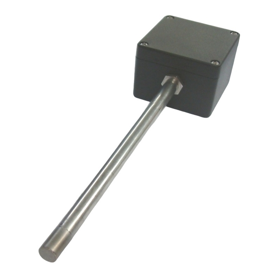
The actual oxygen sensor is mounted in the tip of the stainless-steel probe and is protected by a
stainless-steel sintered cap which acts as both a large particulate filter and also as a flame trap. The
die-cast aluminium housing accommodates the electronics and is mechanically connected to the
sensor probe.
UG-014 Rev 1
)
2
Advertisement
Table of Contents

Related Manuals for SST OXY-Flex


Summary of Contents for SST OXY-Flex
- Page 1 This document describes the installation, operation and maintenance of the OXY-Flex oxygen analyser. The OXY-Flex analyser designed to determine the oxygen concentration in air or inert gas mixtures in areas that are not easily accessible, or in closed systems, such as ventilation pipes, flues and containers: •...
-
Page 2: Table Of Contents
Contents DEFINITIONS ..........................1-1 SAFETY INSTRUCTIONS ......................... 2-1 TECHNICAL SPECIFICATIONS ......................3-1 PRODUCT OVERVIEW ........................4-1 Main Components ........................ 4-1 External Dimensions ......................4-1 INSTALLATION ..........................5-1 Mounting Instructions ......................5-1 Electrical Connections ......................5-2 System Block Diagram ......................5-3 PCB Layout ........................... -
Page 3: Definitions
1 DEFINITIONS The following definitions apply to WARNINGS, CAUTIONS and NOTES used throughout this manual. WARNING: The warning symbol is used to indicate instructions that, if they are not followed, can result in minor, serious or even fatal injuries to personnel. CAUTION: The caution symbol is used to indicate instructions that, if they are not followed, can result in damage to the equipment (hardware and/or software), or a system failure occurring. -
Page 4: Safety Instructions
2 SAFETY INSTRUCTIONS • This equipment may only be installed by a suitably qualified technician in accordance with the instructions in this manual and any applicable standards associated with the country or industry. • Failure to correctly adhere to these instructions may result in serious injury or death and in this regard the manufacturer will not be held liable. -
Page 5: Technical Specifications
3 TECHNICAL SPECIFICATIONS Electrical Specifications • Supply voltage; 24V ±10% • Current consumption; 500mA maximum at 24V Output • Digital output; RS232 • Analogue output; 0 – 10 V ; load 10kΩ minimum 4 – 20mA; load 600Ω maximum Performance Specifications •... -
Page 6: Product Overview
4 PRODUCT OVERVIEW The OXY-Flex analyser is housed in a sealed, die-cast aluminium enclosure with attached oxygen sensor probe and amphenol ecomate connector. 4.1 Main Components Amphenol Ecomate connector Probe type sensor; available in three lengths – 220mm, 400mm & 600mm... -
Page 7: Installation
5 INSTALLATION To ensure the best performance from your equipment, it must be installed correctly. CAUTION: Protect the device from accidental shocks or vibrations as this may damage the board. 5.1 Mounting Instructions Dimensions in mm unless otherwise stated; tolerance ±0.5mm. Figure 5-1 –... -
Page 8: Electrical Connections
5.2 Electrical Connections WARNINGS: All wiring MUST be in accordance with the National Electrical Code and any local codes, ordinances, and regulations. Disconnect and lock out power before connecting the equipment to the power supply. The device wiring should be in a separate conduit. Do NOT install wiring in any conduit or junction boxes with high voltage wiring. -
Page 9: System Block Diagram
5.3 System Block Diagram Figure 5-4 - Block Diagram 5.4 PCB Layout Figure 5-5 - PCB Layout UG-014 Rev 1 Page | 5-3... -
Page 10: Initial Startup
6 INITIAL STARTUP 6.1 Commissioning Checks Before commissioning the equipment read 2 SAFETY INSTRUCTIONS page 2-1 of this document. Complete the following essential tasks BEFORE switching the system ON for the first time: • Ensure compliance with permissible installation position. •... -
Page 11: System Configuration
7 SYSTEM CONFIGURATION The OXY-Flex can be configured to output measuring ranges of 0 – 25% O and 0 – 100% O ; the entire measurement range is linear in both cases. NOTE: Factory default is 0 – 25% O with linear 4-20mA and 0-10V outputs. -
Page 12: Setting The Calibration Type And Measurement Range
7.2 Setting the Calibration Type and Measurement Range The interface board is fitted with two jumper links which set the calibration type (Manual or Automatic) and oxygen measurement range (100% or 25%). These settings may be configured at any time by adjusting the position of the header pin jumper links on the board. WARNING: The equipment MUST be powered OFF. -
Page 13: Digital Variant - Rs232 Output
7.3 Digital Variant – RS232 Output When connecting the OXY-Flex using the RS232 connections ensure Tx goes to Rx of the PC NOTE: and Rx goes to Tx of the PC. The OXY-Flex communicates via standard COM port settings that are default on most PCs and many other RS232 compatible devices. - Page 14 Variable Output Filtering (T Averaging) The OXY-Flex is factory default to use adaptive output filtering to give an optimum balance between output stability and response to oxygen changes. This balance may be altered to suit the needs of your application.
- Page 15 7.3.4 Analogue Output Minimum and Maximum Ranges The OXY-Flex is factory default to output a range of 0 – 25% O via its two analogue outputs. This range can be expanded to 0 – 100% O by repositioning the jumper link as described on page 7-1.
-
Page 16: Analogue Variants - 0-10V Dc And 4-20Ma Output Values
4.06mA 4.02mA NOTE: The analogue output ranges actually represent 0 to 25% or 0 to 100% O however as SST’s oxygen sensors cannot measure below 0.1% O this value is displayed as the range minimum. UG-014 Rev 1 Page | 7-6... -
Page 17: Operation
8.2 RS232 Operation With the OXY-Flex RS232 outputs connected to a PC (or any other RS232 compatible device), you can access two modes of operation; continuous data streaming and the menu screens. Refer to Digital Variant –... -
Page 18: Maintenance
High-pressure water or steam 9.2 Calibrating SST Sensing’s range of zirconium oxygen sensors do not directly measure the oxygen concentration but instead measure the partial pressure of oxygen within the measurement gas. In order to output an oxygen concentration (%) the sensor must be calibrated, or more specifically, re-referenced in a known gas concentration, typically fresh air. - Page 19 9.2.1 Automatic Calibration 1. Ensure the OXY-Flex is configured for automatic calibration. Refer to 7.1 Setting the Calibration Type and Measurement Range page 7-1. 2. Place the sensor probe in the calibration gas, typically fresh air. 3. Allow the output to stabilise for at least 5 minutes (10 minutes if powering from cold).
-
Page 20: Error Conditions
9.3 Error Conditions If the oxygen sensor is incorrectly connected or is damaged, the OXY-Flex will highlight this by blinking the CYCLE output (pin 4) and green LED in a 3 short blinks – 1 long blink pattern or continuously OFF. In addition, an error code displays on the RS232 output and the analogue outputs will default to 4mA and 0V. -
Page 21: Appendix A - Menu Structure
APPENDIX A – MENU STRUCTURE Password Screen Main Menu UG-014 Rev 1 Page | A-1... - Page 22 Diagnostics Screens Diagnostics Main Menu Diagnostics Diagnostics Menu 1. Menu 2. Diagnostics Diagnostics Menu 3. Menu 4. UG-014 Rev 1 Page | A-2...
- Page 23 Configuration Screens Configuration Main Menu Configuration Configuration Menu 1. Menu 2. Configuration Configuration Menu 3. Menu 4. Configuration Menu 5. UG-014 Rev 1 Page | A-3...
- Page 24 Information Screens UG-014 Rev 1 Page | A-4...
- Page 25 SST Sensing Ltd. reserves the right to make changes to product specifications without notice or liability. All information is subject to SST Sensing Ltd.'s own data and considered accurate at time of going to print. SST SENSING LIMITED, 5 HAGMILL CRESCENT, SHAWHEAD INDUSTRIAL ESTATE, COATBRIDGE, UK, ML5 4NS www.sstsensing.com...
Need help?
Do you have a question about the OXY-Flex and is the answer not in the manual?
Questions and answers