
Related Manuals for Socket & See DL 420

Summary of Contents for Socket & See DL 420
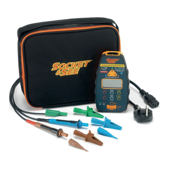
- Page 1 U S E R M A N U A L 0 6 / 0 6 MULTIFUNCTION DIGITAL LOOP TESTER Tests no-trip loop, PFC, socket, mains voltage & polarity DL 420...
- Page 2 If there is any aspect of your Socket & See tester you would like to comment on please visit our website at www.socketandsee.co.uk or email davidh@kewt.co.uk or Free Fax at 0800 7831385 with any suggestions. We promise all communications will be acknowledged. We value YOUR opinion. DL 420...
-
Page 3: Operation Overview
Operation overview Your Socket & See tester has a special polarity test function. It is a little known fact that a system can be reverse wired with Live (Phase) to earth/neutral and earth/neutral to Live (Phase) The sockets will all work and conventional loop testers will show and test that everything is correct despite this very dangerous wiring condition. - Page 4 The DL 420 also has a No-trip test mode that is guaranteed not to trip a 30mA or higher rated RCD providing that the circuit is otherwise healthy.
- Page 5 Lead configuration for No-trip testing This is the default mode that the DL 420 will start in when turned on. This mode is most useful for testing either at socket outlets, luminaires, wiring terminals etc. in installations where the circuit under test may be protected by an RCD.
- Page 6 Test lead configuration Lead configuration for High Current 2-wire testing with TLI feature The TLI function is intended for use at distribution boards and similar points where you are measuring on the supply side of any Switch/RCD gear. The TLI measurement function is selected by pressing button 9 labeled ‘Ze/DB’.
- Page 7 Operation - a detailed view of the DL 420 Note numbers also indicate sequence of test. Three LED’s show socket wiring status LCD (Liquid Crystal Display) display (default L-N voltage measurement) On/off button High current loop impedance No-trip loop test...
-
Page 8: Overview Of The Display
Volts (AC) G. Voltage measurement function L-N (default) L-E and N-E H. Fault current Wait - result calculation in progress Tester has gone over operating temperature K. Battery Condition ( =good) Greater than (>) less than (<) indication DL 420... - Page 9 Loop-PFC testing 1. Power ON/OFF - Pressing and releasing this button turns the DL 420 on - holding down for longer than two seconds turns the unit off (plus intelligent Auto Power Off is incorporated). When the DL 420 is first connected to a live socket it will automatically test the socket wiring to establish that the circuit wires have been connected to the correct terminals on the back of the socket.
- Page 10 The DL 420 will then automatically conduct a Loop test upon connection to the live supply and display the result. The supply voltage can be recalled by pressing the Voltage button.
-
Page 11: Specifications
Specifications Wiring Test Detects missing E or N (>15k ) Detects L-E or L-N swap Detects Live - Earth/Neutral reversal by use of Polarity Test Pad Fault indicated by chart on front of instrument ± 1% ± 1V Phase - Neutral voltage measurement ±... - Page 12 Condition Wiring Supply Buzzer Number Condition Terminal Display Socket Wiring Correct Continuous L-E reverse Warble L-N-E miswire Warble L-N reverse Warble L-N-E miswire Warble Faulty N / L-E miswire Warble Faulty N / E miswire Warble Faulty N Warble Faulty N / L-E reverse Warble Faulty E / L-N reverse Warble...
Need help?
Do you have a question about the DL 420 and is the answer not in the manual?
Questions and answers