Advertisement
Table of Contents
- 1 Table of Contents
- 2 Start Instructions
- 3 Description of Operation and Instructions
- 4 Programming Instructions for Optional Timer
- 5 LSC100 Features and Benefits
- 6 Description of Load Sequencing
- 7 LSC100 Testing Procedure
- 8 Parts List
- 9 Wiring Schematic for Kubota/Lsc100
- 10 Wiring Schematic for Cat/Perkins/Lsc100
- 11 LSC100 Logic Sequence Flow Chart
- Download this manual
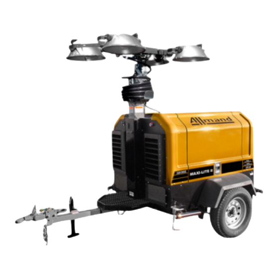
LSC Light Sequence Commander with Timer
Retrofit Kit Installation Instructions for Kubota
LSC100
LIGHT SEQUENCE COMMANDER
Operation, Testing, and
Troubleshooting Information
ALLMAND BROS. INC
P.O. BOX 888
HOLDREGE, NE 68949
PHONE: 308/995-4495, 1-800/562-1373
ALLMAND FAX: 308/995-5887
ALLMAND PARTS FAX: 308/995-4883
LSC100
Light Sequence Commander
1
WI-LSC905-01
Advertisement
Table of Contents

Summary of Contents for Allmand LSC100
- Page 1 LSC Light Sequence Commander with Timer Retrofit Kit Installation Instructions for Kubota LSC100 LIGHT SEQUENCE COMMANDER Operation, Testing, and Troubleshooting Information ALLMAND BROS. INC P.O. BOX 888 HOLDREGE, NE 68949 PHONE: 308/995-4495, 1-800/562-1373 ALLMAND FAX: 308/995-5887 ALLMAND PARTS FAX: 308/995-4883 LSC100 Light Sequence Commander WI-LSC905-01...
-
Page 2: Table Of Contents
LSC100 Features and Benefits ................. Page 6 Description of Load Sequencing ................Page 7 LSC100 Testing Procedure..................Page 8 Parts List ........................Page 9 Wiring Schematic for Kubota/LSC100 ............Pages 10-14 Wiring Schematic for Cat/Perkins/LSC100 ............Pages 15-19 LSC100 Logic Sequence Flow Chart ..............Page 20 WI-LSC905/3003-02... -
Page 3: Start Instructions
Manual Start Instructions 1. Turn power switch ON 2. Turn light circuit breakers ON 3. Turn Auto/Manual switch to MANUAL NOTE: *Glow plugs are automatic as required *Engine will start or make 5 attempts *Lights will come on when engine water temperature reaches 120° F. Shut Down 1. -
Page 4: Description Of Operation And Instructions
The Allmand LSC100 Light Sequence Commander includes an engine auto start controller and a light circuit controller in one package. The LSC100 features 5 LEDs on the face of the control panel indicating the follow- ing from left to right. -
Page 5: Programming Instructions For Optional Timer
PROGRAMMING INSTRUCTIONS FOR OPTIONAL ALLMAND LSC100 TIMER The Allmand LSC100 Light Sequence Commander can be equipped with an optional 7 Day, 8 Event, program- mable timer. OVERVIEW The LSC Timer allows full ON/OFF control of the LSC equipped light tower. The lights can be turned ON and OFF at specific times of the day and as many as 8 times a day. -
Page 6: Lsc100 Features And Benefits
ALLMAND LSC100 LIGHT SEQUENCE COMMANDER Features and Benefits GENERAL DESCRIPTION: The LSC100 Light Sequence Commander includes an engine auto start control and a light circuit controller in one package. The control provides for complete automatic light tower operation once the machine is set up on the job site. -
Page 7: Description Of Load Sequencing
ALLMAND LSC Light Sequence Controller SEQUENCING ON Generally an engine-driven generator is required to start with a load connected. It is not uncommon for the load to be applied to the generator all at one time as the engine is coming up to speed. It is also common for a generator set to have a fixed RPM in order to maintain a required frequency, usually 1800 or 3600 RPM. -
Page 8: Lsc100 Testing Procedure
LSC Light Sequence Commander Testing Procedure The following information can be used for diagnostic evaluation and testing: 1. Overcrank: Remove the yellow 16 ga. wire from the starter. Place the power switch to the ON position and place the Auto/Manual switch to manual. After 5 start attempt cycles of the crank relay, the fuel and crank relay will remain open and the red alarm LED will flash. -
Page 9: Parts List
Parts List LSC100 Microprocessor Control Parts List Description Part Number Controller LT100 mounted on vibration isolators with triple pole toggle switch 650744 Temperature sender 3/8” NPT 650745 Engine harness 650746 Red LED lens 650747 Green LED lens 650748 Yellow LED lens... -
Page 10: Wiring Schematic For Kubota/Lsc100
Wiring Schematic for Kubota LSC100 LIGHT SEQUENCE CONTROLLER with Photocell and Optional Timer WI-LSC905/3003-02... - Page 11 Wiring Schematic for Kubota LSC100 LIGHT SEQUENCE CONTROLLER with Photocell and Optional Timer WI-LSC905/3003-02...
- Page 12 Wiring Schematic for Kubota LSC100 LIGHT SEQUENCE CONTROLLER with Photocell and Optional Timer WI-LSC905/3003-02...
- Page 13 Wiring Schematic for Kubota LSC100 LIGHT SEQUENCE CONTROLLER with Photocell and Optional Timer WI-LSC905/3003-02...
- Page 14 Wiring Schematic for Kubota LSC100 LIGHT SEQUENCE CONTROLLER with Photocell and Optional Timer WI-LSC905/3003-02...
-
Page 15: Wiring Schematic For Cat/Perkins/Lsc100
Wiring Schematic for Cat/Perkins LSC100 LIGHT SEQUENCE CONTROLLER with Photocell and Optional Timer WI-LSC905/3003-02... - Page 16 Wiring Schematic for Cat/Perkins LSC100 LIGHT SEQUENCE CONTROLLER with Photocell and Optional Timer WI-LSC905/3003-02...
- Page 17 Wiring Schematic for Cat/Perkins LSC100 LIGHT SEQUENCE CONTROLLER with Photocell and Optional Timer WI-LSC905/3003-02...
- Page 18 Wiring Schematic for Cat/Perkins LSC100 LIGHT SEQUENCE CONTROLLER with Photocell and Optional Timer WI-LSC905/3003-02...
- Page 19 LSC100 LIGHT SEQUENCE CONTROLLER Logic Sequence Flow Chart WI-LSC905/3003-02...
-
Page 20: Lsc100 Logic Sequence Flow Chart
WI-LSC905/3003-02...
Need help?
Do you have a question about the LSC100 and is the answer not in the manual?
Questions and answers