
Subscribe to Our Youtube Channel
Summary of Contents for Technische Alternative CAN-MTx2-CO2
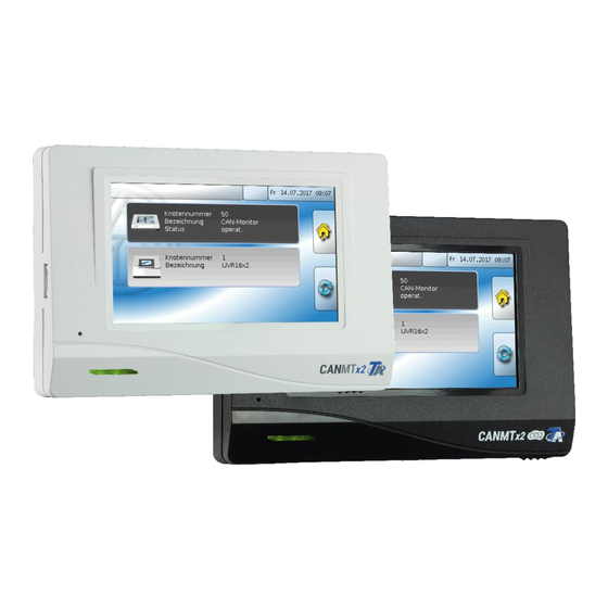
- Page 1 CAN-MTx2 CAN-MTx2-CO2 CAN Monitor Instruction manual Manual version 1.18.1 English...
-
Page 3: Table Of Contents
Table of contents Version 1.18.1 EN Safety requirements ..........................5 Maintenance .............................. 5 Disposal ...............................6 Principles.............................6 Installing and connecting the device ....................7 Installing the device ..........................7 Dimensions ............................7 Power supply ............................. 8 CAN bus connection ..........................8 CAN bus cable selection and network topology ..................8 User manual - Technician / Expert .......................9 Function overview display ........................ - Page 4 Current user ............................27 Changing the password ........................28 List of permitted actions........................28 Version and serial number........................29 Data administration ..........................30 Function data ............................30 Load..............................31 Deleting, renaming and sending saved files ................32 Save..............................33 Firmware Load...
-
Page 5: Safety Requirements
Safety requirements These instructions are intended exclusively for authorised contractors. All installation and wiring work on the device must only be carried out in a zero volt state. The opening, connection and commissioning of the device may only be carried out by competent personnel. -
Page 6: Disposal
They must never be treated as ordinary household waste. ➢ We can undertake the environmentally responsible disposal of devices sold by Technische Alternative upon request. ➢ Packaging material must be disposed of in an environmentally responsible manner. -
Page 7: Installing And Connecting The Device
Installing and connecting the device Installing the device The device must only be installed in a dry interior room. For correct detection of the room tempera- ture, the CAN monitor must always be installed vertically. Permissible ambient temperature: +5°C - +45°C Press the two locking clamps on the left and right and lift the cover. -
Page 8: Power Supply
Power supply The CAN monitor requires a 12 V power supply originating from a freely programmable controller (UVR16x2 or RSM610). No more than three devices (CAN monitor, CAN-I/O module etc.) can be sup- plied from each controller. With 4 or more devices in the CAN network, a 12 V power unit is required. CAN bus connection The screwless terminals for the CAN bus are located in the base of the CAN monitor. -
Page 9: User Manual - Technician / Expert
User manual - Technician / Expert If a function overview was loaded onto the CAN monitor, the display will show the function overview once it is connected to the CAN bus. The function overview can be programmed as standard view or full screen view. Function overview display Standard view Example:... -
Page 10: Full Screen View
Full screen view In the full screen view, the upper status bar and the side buttons are hidden. Example: Start page with 4 links If you press the background image for 3 seconds, 4 buttons appear which enable access to the ver- sion information of the CAN monitor, the general settings or the date, time and location settings, and the main menu of the CAN monitor. -
Page 11: Main Menu
Main menu • Inputs – The CAN-MT16x2 CAN monitor has a sensor for temperature and humidity • Messages – Sensor and network errors from the CAN-MTx2 are displayed here • CAN BUS – CAN settings, definition of CAN inputs and outputs •... -
Page 12: Date / Time / Location
Date / time / location The "Date" and "Time" are shown in the status line at top right. As the CAN monitor does not have its own clock function, the time and date are taken from network node 1 and cannot be changed in the CAN monitor. For this reason, at least one CAN bus device which has its own clock function must have the node number 1 (UVR16x2, UVR1611, RSM610, C.M.I.). -
Page 13: Inputs
The values for geographical latitude and longitude are used to determine the location-specific solar data. That data can be used in functions (e.g. shading function). The factory default settings for the GPS data are for the location of Technische Alternative in Amaliendorf, Austria. -
Page 14: Sensor Correction
Sensor correction The option of sensor correction is available for the measured variables The corrected value is utilised for all calculations and displays. Example: Average This setting refers to the average of the measurements over time. Averaging over 0.3 seconds leads to extremely rapid reactions on the part of the display and the unit. However, this can be expected to cause fluctuations of the value. -
Page 15: Sensor Error
Sensor error When "Sensor check" is active, Sensor error is available as the source for digital CAN outputs: status "No" for a sensor that is working correctly and "Yes" for a defect (short circuit or lead break). This allows the controller to react to the failure of a sensor, for example. In System values / General, a sensor error for all inputs is available. -
Page 16: Messages From Other X2 Devices
Messages from other x2 devices Depending on the setting in the x2 device, messages from other x2 devices can be displayed on the CAN monitor with a pop-up window, a changed status LED and/or a warning tone. The pop-up window works in the same way as on the display of the UVR16x2 controller. Example: Message type "Error";... -
Page 17: Internal Can Monitor Messages
Internal CAN monitor messages The "Messages" menu displays messages that are caused by sensor or CAN bus errors in the CAN- MTx2. Message from other x2 devices are not displayed here. Example: Fault on input 1 If at least one internal message is active, the warning symbol will appear in the upper status line on the right. -
Page 18: Can Bus
CAN bus The CAN network allows communication between CAN bus devices. When analogue or digital values are sent via CAN outputs, other CAN bus devices can utilise those values as CAN inputs. Up to 62 CAN bus devices can be operated in one network. Every CAN bus device must be given its own node number in the network. -
Page 19: Datalogging
Datalogging This menu cannot be selected in the User mode. This menu is used to define the parameters for CAN datalogging of analogue and digital values. CAN datalogging requires at least version 1.25 on the C.M.I. datalogger and a Winsol version of at least 2.06. -
Page 20: Can Settings
CAN settings Node Define a unique CAN node number for the device (setting range: 1 – 62). The factory-set node number of the CAN-MTx2 is 50. Designation Every device can be given its own designation. Bus rate The standard bus rate of the CAN network is 50 kbit/s (50 kBd), which is specified for most CAN bus devices. -
Page 21: Can Analogue Outputs
CAN analogue outputs The 5 analogue inputs are already linked to the first five CAN analogue outputs. In CAN-MTx2 (without CO sensor), the fifth value is always 0. As there are no other analogue values available as the source for CAN analogue outputs, no instruc- tions are given here for programming other CAN analogue outputs. -
Page 22: Can Digital Outputs
CAN digital outputs They are defined by specifying the source in the CAN monitor. Example: Source "Sensor error inputs" Designation Every CAN digital output can be given its own designation. The designation can be selected from var- ious designation groups or can be user defined. Example: Transmission condition Example:... -
Page 23: Active Can Nodes
Active CAN nodes Tapping the button displays the active CAN nodes in the CAN bus network. "Status" displays the CAN bus status of the CAN monitor. After starting, the status changes automati- cally, according to a predefined process, from init. → preop(erational) → operat(ional). Only then is it possible to communicate with other CAN bus devices. -
Page 24: General Settings
General settings Displayed in Expert mode only Displayed in Technician or Ex- pert mode only This menu allows settings to be made which then take effect for all other menus and displays. Language Select the display language Brightness Select the brightness of the display to match the surroundings (setting range: 5.0 – 100.0 % Display timeout The display will be switched off if the user does not do anything for the period of time set here. -
Page 25: Simulation
Simulation No application possibility for the CAN-MTx2 Access to menu Definition of the user level from which access to the CAN monitor's main menu is permitted. If only technicians or experts are permitted to access the menu, then the relevant password must be entered when selecting the main menu from the start page of the function overview ( button). -
Page 26: User Defined Designations
User defined designations In this menu, you can enter, change or delete user defined designations for all elements of the CAN monitor. This menu can only be selected from within the Technician or Expert level. View with designations defined previously An alphanumeric keyboard is provided for changing a designation or creating a new one. -
Page 27: User
User Current user Select whether the user is an Expert, Technician or User. To enter the Technician or Expert level a password must be entered, which can be set by the pro- grammer. Following a restart, the CAN monitor is always in the User level. -
Page 28: Changing The Password
Changing the password An Expert can change the passwords for Technician and Expert. A Technician can only change the Technician password. There are no restrictions regarding the length of the password or the type of characters that can be used. To change a password, you must first en- ter the old password. -
Page 29: Version And Serial Number
Version and serial number The display shows the serial number, internal production data and the names of the current function data and function overview. V 1.01 MTX2-000000... -
Page 30: Data Administration
Data administration Only visible in Technician or Expert mode You can perform the following actions in this menu: • Save, load or delete function data • Load firmware • Load or delete a function overview • Display the status of the data transfer Function data Display the current function data with the time of loading... -
Page 31: Load
Load... Function data can be loaded from the SD card onto the CAN monitor or other X2 devices. More than one set of function data can be saved on the SD card. The data transfer is only possible after a technician or expert password has been entered for the tar- get device. -
Page 32: Deleting, Renaming And Sending Saved Files
Deleting, renaming and sending saved files In order to rename or delete a saved file, tap the plus icon. The following options then appear for se- lection: Delete file Rename file Send file to selected nodes Return from this selection by tapping the plus icon again. Delete file A confirmation prompt appears, which you can confirm by tapping Tapping... -
Page 33: Save
Save... The current function data of the CAN monitor can be backed up on the SD card. You can give the function data a name of your own. More than one set of function data can be saved. Example: In this example there are already several sets of function data saved on the SD card. If you want to save the function data under a new name, tap the button. -
Page 34: Firmware Load
Firmware Load... Firmware (= operating system, file *.bin) can be loaded from the SD card onto the CAN monitor or other X2 devices on the CAN bus (exception: UVR16x2). More than one operating system version may be saved on the SD card. The data transfer is only possible after a technician or expert password has been entered for the tar- get device. -
Page 35: Status
Status This indicates whether a data administration transfer of data from the SD card to the CAN monitor or vice versa was successful or not. This status display does not apply to data transfers from another controller, a C.M.I. or another CAN monitor. -
Page 36: Restart
Restart At the end of the "Data admin" menu, there is an option to restart the moni- tor following a confirmation prompt, without disconnecting the monitor from the network. LED indicator light LED indicator light LED status indicators at start Indicator light Explanation Steady red light... -
Page 37: Reset
Reset Pressing the reset button on the front of the CAN monitor briefly (with a narrow-tip pen) and releasing it before the beep ends will restart the CAN monitor (= reset). Loading the firmware with the factory settings In special cases, it may be necessary to restore the CAN moni- tor's firmware to its condition when delivered from the factory. -
Page 38: User Manual - Final User
User manual - final user The CAN-MTx2 CAN monitor is used as a control and display unit for the freely programmable con- trollers UVR16x2 and RSM610 as well as all other devices in the X2 series. The CAN monitor has a combined temperature and humidity sensor built in and can therefore also be used as a room sensor. -
Page 39: User Levels
User levels To prevent incorrect operation of the controller, three different user groups can log onto the controller: User, Technician or Expert. Access by Technicians and Experts requires a password. User Displays and permitted actions • Function overview with options for control •... -
Page 40: Function Overview
Function overview The function overview is freely designed by the programmer and can therefore look different on every system. It can be displayed with the aid of graphics or simply as a table. Values selected by the programmer can be changed either by all users, by Experts only or by Experts and Technicians. -
Page 41: Full Screen View
If you press the background image for 3 seconds, 2 buttons appear which serve to access the version information and the general settings respectively. V 1.01 MTX2-000000 You can go back to the page displayed previously by tapping Full screen view In the full screen view, the upper status bar and the side buttons are hidden. - Page 42 If you press the background image for 3 seconds, 4 buttons appear which enable access to the ver- sion information of the CAN monitor, the general settings or the date, time and location settings, and the main menu of the CAN monitor. This button takes you to the main menu of the CAN monitor.
- Page 43 EU Declaration of conformity Document- Nr. / Date: TA17030 / 02/02/2017 Company / Manufacturer: Technische Alternative RT GmbH Address: A- 3872 Amaliendorf, Langestraße 124 This declaration of conformity is issued under the sole responsibility of the manufacturer. Product name: CAN-MTx2, CAN-MTx2-CO2...
- Page 44 2. The guarantee includes free repair (but not the cost of on-site fault finding, removal, refitting and shipping) due to operational and material defects which impair operation. In the event that a repair is not economical in the opinion of Technische Alternative for reasons of cost, the goods will be replaced.
Need help?
Do you have a question about the CAN-MTx2-CO2 and is the answer not in the manual?
Questions and answers