Table of Contents
Advertisement
Quick Links
Advertisement
Table of Contents

Summary of Contents for UAB Enilit Enilit RTU
- Page 1 Enilit RTU User manual Copyright UAB Enilit. All rights reserved, 2010 – 2018...
-
Page 2: Table Of Contents
2.3.2 Disposal ........................... 10 2.4 Declaration of conformity ....................... 10 2.5 Handling of electronic equipment ....................12 2.6 Warnings regarding use of UAB Enilit products ................12 2.7 Guarantees ............................13 2.8 Copyright ............................14 Enilit RTU Hardware .......................... 15 3.1 System Conception ......................... - Page 3 3.16 Order-book ............................51 3.16.1 Basic frame ......................... 51 3.16.2 Second frame........................54 Enilit RTU software ..........................55 4.1 Introduction ............................. 55 4.2 System capabilities .......................... 55 4.3 Licensing ............................56 4.4 User interface ..........................57 4.5 Configurator ............................ 62 4.5.1 User groups ..........................
- Page 4 DNP3 serial slave configuration ..................218 4.11.4 DNP3 UDP/TCP/IP server configuration ................. 230 4.11.5 SPA-BUS configuration ....................233 4.11.6 RP-570 configuration ......................242 4.12 TAG Manager ..........................250 4.12.1 Tag states........................... 256 Page 4 of 309 Enilit RTU User Manual 16.09...
- Page 5 4.17.1 Redundancy support ......................289 4.17.2 Redundancy types ......................289 4.17.3 Connection diagram ......................289 4.17.4 Enilit RTU redundancy principles ..................290 4.17.5 Monitored fault locations ....................291 4.17.6 Redundancy configuration ....................291 4.17.7 Communication channel configuration ................293 4.17.8 Status signals, commands and measurements ..............
-
Page 6: Introduction
At the same time, the growing demands of utility owners for more cost-effective control systems must be met. Enilit RTU is our solution for automation applications. The modular and open structure of the Enilit RTU system sets wide range where it could be used: ... - Page 7 Time-saving, user-optimized parameterization with minimum effort Enilit RTU Configuration and management software (CMS) with Microsoft Windows operating system or Linux, Open interfaces which permit connection of peripheral units (e.g. printer or operator panel).
-
Page 8: Safety
Introduction This documentation includes information for qualified technical personnel. It describes the safety, handling, packing and unpacking procedures applicable to Enilit RTU hardware and software tools. Health and safety THIS SAFETY SECTION SHOULD BE READ BEFORE COMMENCING ANY WORK ON THE EQUIPMENT. -
Page 9: Electrical Connections
The recommended maximum rating of the external protective fuse for this equipment is: Supply voltage Fuse, A 48VDC 110VDC 220VDC 110VAC 230VAC For the supply of the feeder voltage please use cables with the 1.5 mm² cross section. Page 9 of 309 Enilit RTU User Manual 16.09... -
Page 10: Terminals
Decommissioning and disposal 2.3.1 Decommissioning The auxiliary supply circuit in the Enilit RTU may include capacitors across the supply or to earth. To avoid electric shock or energy hazards, after completely isolating the supplies to the Enilit RTU (both poles of any dc supply), the capacitors should be safely discharged via the external terminals prior to decommissioning. - Page 11 Dry heat (70°C for 24 h) EN 60068-2-2:2007 EN 60068-2-6:2008 Vibration (2g, 10-500Hz, 1 octave/min, 10 sweep cycles) Damp heat, steady state (95% RH and 40°C for 48 h) EN 60068-2-78:2013 Page 11 of 309 Enilit RTU User Manual 16.09...
-
Page 12: Handling Of Electronic Equipment
Warnings regarding use of UAB Enilit products UAB Enilit products are not designed with components and testing for a level of reliability suitable for use in connection with surgical implants or as critical components in any life support systems whose failure to perform can reasonably be expected to cause significant injuries to a human. -
Page 13: Guarantees
Customer's rights to recover damages caused by fault or negligence on the part UAB Enilit shall be limited to the amount therefore paid by the customer. UAB Enilit will not be liable for damages resulting from loss of data, profits, use of products or Page 13 of 309 Enilit RTU User Manual 16.09... -
Page 14: Copyright
This limitation of the liability of UAB Enilit will apply regardless of the form of action, whether in contract or tort, including negligence. Any action against UAB Enilit must be brought within one year after the cause of action accrues. -
Page 15: Enilit Rtu Hardware
Enilit RTU Hardware System Conception Enilit RTU is a modular, freely scalable remote control and automation device. Its field of application is the fully-automatic monitoring and control of decentralized process stations or RTUs (e.g. in medium voltage switches bays). Plug-in I/O modules serve for process connection, and communication modules are available for the additional connection of subsystems (e.g. -
Page 16: Rack Mounting And Frame
Rack mounting and Frame Enilit RTU frame consists of a metal housing, an internal bus system and plug-in system components. A standard RTU includes at least a power supply module and a central processor module. Maximum number of 12 slots for I/O and communication modules is available. - Page 17 Enilit RTU Hardware Rack mounting and Frame Standard or extended frame front view Standard or extended frame top view Page 17 of 309 Enilit RTU User Manual 16.09...
-
Page 18: Short Hardware Review
Enilit RTU Hardware Short hardware review Small frame front and top view Short hardware review The remote terminal unit “Enilit RTU” device comes in one basic 6U frame system, protection class IP- 20. One frame can include: two power supply modules, ... -
Page 19: Power Supply Module
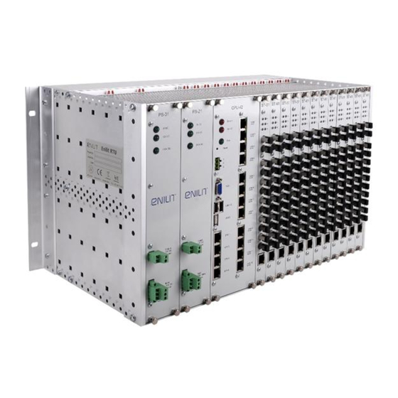
Enilit RTU Hardware Short hardware review Explanation Power supply module Central processor module I/O modules Front view of Enilit RTU 3.3.1 Power Supply Module There is four type of power supply module available: Application Module Input voltage 115V AC PS-11... -
Page 20: Additional Features
External VGA compatible monitor, keyboard and mouse for RTU monitoring, management and configuration. External Touch Screen monitor for one or several feeders visualization and control (HMI). Computer with SCADA for local substation management. Protocol converter (gateway). Page 20 of 309 Enilit RTU User Manual 16.09... -
Page 21: Central Processor Unit Module Cpu
8 x RS485 Serial links (RJ45) 4x Ethernet (RJ45), CPU-43 8 x RS232 Serial links (RJ45), 4 x RS485 Serial links (RJ45) 4x Ethernet (RJ45), CPU-44 12 x RS232 Serial links (RJ45) Page 21 of 309 Enilit RTU User Manual 16.09... - Page 22 Hardware configuration LED indicator Error1 mistake in hardware status configuration Error2 User defined LED is BLINKING - LED indicator CPU status device is OK (running) Push button Reset Manually reset device by Page 22 of 309 Enilit RTU User Manual 16.09...
- Page 23 Connect control centers or ETH1-ETH4 interface socket RJ- protection devices Note. If Error1 and Error2 LEDs lights up and RUN LED is OFF, that means CPU error or system is starting. Page 23 of 309 Enilit RTU User Manual 16.09...
-
Page 24: Serial Communication Interface (Rj-45)
The status of each communication interface is shown via the two software-controlled LEDs that are installed in the connectors. The yellow LED is activated during transmission of data in the transmission direction. The green LED is activated during transmission of data in the receive direction. Page 24 of 309 Enilit RTU User Manual 16.09... -
Page 25: Ethernet Interface (Rj-45)
The yellow LED is activated during transmission of data in the transmission or the receive direction. 3.5.3 Parallel Redundancy Protocol (PRP) Parallel Redundancy Protocol (PRP) is supported by Enilit RTU and no additional equipment is required. PRP is a network protocol standard for Ethernet that provides seamless failover against failure of any network component. -
Page 26: Technical Data
Device is turned off; Error Enilit CMS is closed and Watchdog relay time out timer ended; Error RTU hardware configuration state has abnormal card states; Error RTU has detected a hardware error. Terminal Function Page 26 of 309 Enilit RTU User Manual 16.09... -
Page 27: Power Supply Module
Max power for this output is 3 Amps. In one Enilit RTU can be installed two power supply units whose one can work from different voltages: one from AC and another from DC supply voltage at the same time. -
Page 28: Wiring Diagram
LED is ON - voltage is OK 110V DC, 220V DC Input voltage connection terminals 12V DC output connection terminals 3.6.1 Wiring diagram Function Terminal Voltage Voltage L(+) N(-) Ground Ground Power supply wiring diagram Page 28 of 309 Enilit RTU User Manual 16.09... -
Page 29: Technical Data
Frequency range 47 ~ 63Hz Current (Typ.) 3A/115V 2A/230V Inrush current (Typ.) COLD START 40A/230V Leakage current <2mA / 240VAC -25 ~ +85°C Working temperature Working humidity 0 ~ 95% RH non-condensing Page 29 of 309 Enilit RTU User Manual 16.09... -
Page 30: Digital Input Module
LED is OFF – input is inactive; LED indicators for Digital input status ALL LEDS are blinking together – no connection each digital input with CPU or digital input board error. Connection terminals Page 30 of 309 Enilit RTU User Manual 16.09... -
Page 31: Wiring Diagram
DI 3 DI 4 DI 5 DI 6 DI 7 DI 8 DI10 DI11 DI12 DI13 DI14 DI15 DI16 DI17 DI18 DI19 DI20 DI21 DI22 DI23 DI24 Digital input board wiring diagram Page 31 of 309 Enilit RTU User Manual 16.09... -
Page 32: Technical Data
2.5 kV ; 50 Hz, 1 min 4.4 kV; 1.2/50 μs; 0.5 J - Surge voltage Power consumption for binary input logical "1" 1 - 3 mA (depending on used Voltage). Page 32 of 309 Enilit RTU User Manual 16.09... -
Page 33: Digital Output Module
LED is OFF – output is inactive; LED indicators for Digital output ALL LEDS are blinking together – no connection each digital output status with CPU or digital output board error. Connection terminals Page 33 of 309 Enilit RTU User Manual 16.09... -
Page 34: Wiring Diagram
Enilit RTU Hardware Digital Output Module 3.8.1 Wiring diagram Function Function DO10 DO11 DO12 DO13 DO14 DO15 DO16 DO17 DO18 DO19 DO20 DO21 DO22 DO23 DO24 Digital output board wiring diagram Page 34 of 309 Enilit RTU User Manual 16.09... -
Page 35: Technical Data
3 ... 220 V Increased insulation resistance acc. to IEC 60255-5 - Power-frequency withstand voltage 2.5 kV ; 50 Hz, 1 min 4.4 kV; 1.2/50 μs; 0.5 J - Surge voltage Page 35 of 309 Enilit RTU User Manual 16.09... -
Page 36: Analogue Input Module Ai-31
The AI-31 analogue input module serves for the processing of up to twelve analogues, current or voltage input signals. Note. Measuring current or voltage can be selected for each input separately by the internal jumper position. Analogue input board front and side view Page 36 of 309 Enilit RTU User Manual 16.09... - Page 37 LED is ON – measured value is under or over LED indicators for Analogue input range, each analogue input status ALL LEDS are blinking together – no connection with CPU or analog input board error. Connection terminals Page 37 of 309 Enilit RTU User Manual 16.09...
-
Page 38: Wiring Diagram
Analogue input 9+ Analogue input 9- Analogue input 10+ Analogue input 10- Analogue input 11+ Analogue input 11- Analogue input 12+ Analogue input 12- Ground Ground Analogue input board wiring diagram Page 38 of 309 Enilit RTU User Manual 16.09... -
Page 39: Technical Data
Acquisition cycle max. 100 ms Increased insulation resistance acc. to IEC 60255-5 - Power-frequency withstand voltage 2.5 kV ; 50 Hz, 1 min 4.4 kV; 1.2/50 μs; 0.5 J - Surge voltage Page 39 of 309 Enilit RTU User Manual 16.09... -
Page 40: Transducer Less Measurements Module Ac-31
LED is ON – measured value is under or over LED indicators for Measurement input range, each input status ALL LEDS are blinking together – no connection with CPU or analog input board error. Connection terminals Page 40 of 309 Enilit RTU User Manual 16.09... -
Page 41: Wiring Diagram
V4 voltage input V4 V4 voltage input 04 V5 voltage input V5 V5 voltage input 05 V6 voltage input V6 V6 voltage input 06 Ground Ground Measurement input board wiring diagram Page 41 of 309 Enilit RTU User Manual 16.09... -
Page 42: Technical Data
Acquisition cycle max. 100 ms Increased insulation resistance acc. to IEC 60255-5 - Power-frequency withstand voltage 2.5 kV ; 50 Hz, 1 min 4.4 kV; 1.2/50 μs; 0.5 J - Surge voltage Page 42 of 309 Enilit RTU User Manual 16.09... -
Page 43: Glass Fiber Optic Module St-61
50/125 µm, 62.5/125 µm, 100/140 µm, and 200 µm. Two fibers are required between the two devices, one each direction of data. Glass fiber optic board Page 43 of 309 Enilit RTU User Manual 16.09... - Page 44 5 - 6 pins should be TX - TA - DA - linked together Not used Not used Not used Not used Not used Not used a) ST-61 side b) Cable side RJ45 connector Page 44 of 309 Enilit RTU User Manual 16.09...
-
Page 45: Plastic Fiber Optic Module Pl-61
The PL-61 uses a separate LED emitter and photo-detector operating at an 660 nm wavelength. Connections to the emitter and detector are done with PL type connectors. Two fibers are required between the two devices, one each direction of data. Glass fiber optic board Page 45 of 309 Enilit RTU User Manual 16.09... - Page 46 5 - 6 pins should be TX - TA - DA - linked together Not used Not used Not used Not used Not used Not used b) PL-61 side b) Cable side RJ45 connector Page 46 of 309 Enilit RTU User Manual 16.09...
-
Page 47: Communication Module Cd-61, Ck-61
The CD-61, CK-61 is designed to provide communication from six RS-232/485 ports to one RS-232/485 serial port. The serial communication interfaces (RS-232 or RS-485) are designed as 8-pole RJ45 connector. Com port boards CK-61, CD-61 Page 47 of 309 Enilit RTU User Manual 16.09... - Page 48 The yellow LED is activated during transmission of data in the transmission direction. The green LED is activated during transmission of data in the receive direction. Page 48 of 309 Enilit RTU User Manual 16.09...
-
Page 49: Ethernet Communication Module Lan-21
Ethernet communication module LAN-21 The Ethernet communication module LAN-21 is designed to provide 2 Ethernet type ports. The ethernet 10/100 base TX communication interface is designed as 8-pole RJ45 connector. Ethernet communication module LAN-21 Page 49 of 309 Enilit RTU User Manual 16.09... -
Page 50: Installation Of System Housing
Note. The RTUs should be installed in a dry, clean environment with an ambient temperature range of 0 °C ... + 60 °C (standard) and an air humidity of 0 … 95 % (non-condensation). Page 50 of 309 Enilit RTU User Manual 16.09... -
Page 51: Order-Book
Inputs / outputs boards DI-11, 24 x DI, operating voltage 24 VDC DI-21, 24 x DI, operating voltage 48 VDC DI-31, 24 x DI, operating voltage 110 VDC DI-41, 24 x DI, Page 51 of 309 Enilit RTU User Manual 16.09... - Page 52 Without communication protocol PLC Automation Enabled ISaGRAF run- time for Programmable Logic, Automation, etc. Disabled Frame With second frame Without second frame Accessories Wall mounted adapter Ethernet cable for any connection Page 52 of 309 Enilit RTU User Manual 16.09...
- Page 53 ISaGRAF software PLC Editor Manuals: Technical and Operation guides in English Technical and Operation guides in German Technical and Operation guides in Russian Technical and Operation guides in Lithuanian Page 53 of 309 Enilit RTU User Manual 16.09...
-
Page 54: Second Frame
ST LAN 21, 2 Ethernet RJ45 Without board Accessories Wall mounted adapter Ethernet cable for any connection Cache for empty slots Connectors (3 points) Connectors (9 points) Connectors (12 points) Page 54 of 309 Enilit RTU User Manual 16.09... -
Page 55: Enilit Rtu Software
DNP3 serial o DNP3 IP o SPA-BUS o RP-570 o ICP DCON Enilit RTU can be used as gateway between the IEC61850 substation bus and SCADA protocols IEC 60870-5-101 and -104. System capabilities Enilit RTU CMS capabilities: Page 55 of 309... -
Page 56: Licensing
Up to 96 serial slave devices Licensing Enilit RTU CMS software is included by default. Linux or Windows 7 Embedded operating system license is included in the Enilit RTU price. IsaGRAF license can be added by the request. Enilit RTU Substation and SCADA system concept Page 56 of 309 Enilit RTU User Manual 16.09... -
Page 57: User Interface
RTU. You can make changes on a working system without losing connection to other systems. In the Main window you can save Enilit RTU configuration to the hard disk. - Page 58 Click to save configuration. Click to close Enilit RTU software. The following figure shows the standard perspective of the program window of Enilit RTU CMS. The display and work area is subdivided into several views. As is usual with all Windows applications, all windows can be resized, moved or closed.
- Page 59 The following figure shows popup menu of first tree item (CPU).Menu items: Menu item Description Expand All Expand all tree branches Collapse All Collapse all tree branches Page 59 of 309 Enilit RTU User Manual 16.09...
- Page 60 The new tree item will appear in the communications tree. Popup menu is fast and simple way for creating RTU communications. The following window shows Select New Master protocol window. Select New Master protocol window The following window shows Select New Slave protocol window. Page 60 of 309 Enilit RTU User Manual 16.09...
- Page 61 Enilit RTU software User interface Select New Slave protocol window TAG Manager window Page 61 of 309 Enilit RTU User Manual 16.09...
-
Page 62: Configurator
Serial ports, Ethernet ports, OPC, Isagraf, Redundancy Service, Graphics, Logs, Debug and other. Configurator window File menu Menu item Description Log On Log on as a user. Log Off Log off currently logged user. Save (Ctrl+S) Save configuration Exit Exit Configurator Page 62 of 309 Enilit RTU User Manual 16.09... -
Page 63: User Groups
To create Enilit user groups in Windows user group list you can use Enilit Configurator. Run Enilit Configurator program and select from the menu Edit, then Create Enilit user groups. Successful creation shows the following figure. You can use this function without log in. Page 63 of 309 Enilit RTU User Manual 16.09... -
Page 64: Create User With Rights
Users and Groups. Create new user in Users folder, like shown in following figure. Computer management window In the General tab of Enilit User properties uncheck User must change password at next logon checkbox, and check Password never expires checkbox. Page 64 of 309 Enilit RTU User Manual 16.09... - Page 65 Enilit RTU software Configurator Enilit user password options After that open created user properties window and click Member Of tab, then Add new Groups. Page 65 of 309 Enilit RTU User Manual 16.09...
- Page 66 Enilit RTU software Configurator User properties window Click Advanced. Select group window Select all Enilit user groups and click OK. Page 66 of 309 Enilit RTU User Manual 16.09...
- Page 67 CMS. User with all three groups will have full access to the Enilit CMS software, but if you need users with different access level you can add only Enilit Users or Enilit Allow Edit. Page 67 of 309 Enilit RTU User Manual 16.09...
-
Page 68: Users Authentication
RTU with current configuration. After user log on you will see in the Main window user name which have logged on. The following figure shows that logged on user: Enilit. Logged on user Page 68 of 309 Enilit RTU User Manual 16.09... -
Page 69: Project Manager
4.7.1 Basic information With the help of Enilit Project Manager you can manage Enilit RTU configurations. It allows import/export project of Enilit RTU configuration. You can have here many projects and start Enilit CMS with specific RTU configuration. Enilit Project Manager project parameters window... - Page 70 Empty Name Redundant RTU IP address of redundant RTU Empty Redundant RTU Second IP address of redundant RTU Empty File menu Menu item Description Log On Log on as a user. Page 70 of 309 Enilit RTU User Manual 16.09...
- Page 71 Delete Delete branch, project or RTU Project menu Menu item Description Start project Start Enilit RTU CMS with the selected project Edit RTU configuration Edit Enilit RTU configuration with CMS Show Project directory Opens project directory Go to startup project...
-
Page 72: Import Project
With the Export project feature you can export project to external, network or other storage for RTU configuration backup. Export project window Menu item Description Destination directory Where to save exported project Project name File name of exported project (in our case Test.ezip) Page 72 of 309 Enilit RTU User Manual 16.09... -
Page 73: Main Configuration
Windows applications without need of any third party applications. 4.8.1 IP addresses Enilit RTU by default has four Network adapters. Network adapters are independent and each has own MAC address. In that case all Network adapters can have different IP address with a different gateway. - Page 74 6. Select Internet Protocol Version 4 (TCP/IPv4) and click on Properties. 7. Select Use the following IP address and enter the following IP address and subnet mask: IP address: 172.17.217.130 Subnet mask: 255.255.255.0 Gateway: 172.17.217.254 Page 74 of 309 Enilit RTU User Manual 16.09...
-
Page 75: Remote Management
Main configuration 4.8.2 Remote management Enilit RTU can be configured and managed not only locally, but also remotely. If you have TCP/IP connection to Enilit RTU, you can connect to it with Remote Desktop Connection application from Windows Operating System or using Web browser (Internet explorer, Google Chrome etc) when in Enilit RTU is installed UltraVNC server or similar software. - Page 76 Names to Select field, and then click Check Names. If matches are found, select the account you want to use and then click OK. If no matches are found, update the name you entered and try searching again. Repeat this step as necessary, and then click OK. Page 76 of 309 Enilit RTU User Manual 16.09...
- Page 77 7. Click OK twice when you have finished. 4.8.2.2 To connect to Enilit RTU 1. Go to Start>All Programs>Accessories>Remote Desktop Connection 2. Enter the Computer Name or IP address of the Enilit RTU you wish to connect to. Page 77 of 309 Enilit RTU User Manual 16.09...
- Page 78 For more information on specific tabs, click on Help. 4. Click on Connect. 5. Enter your log in credentials of a user account on the Enilit RTU that is allowed to do a remote desktop connection. Page 78 of 309...
- Page 79 Enilit RTU software Main configuration Default username: EnilitRemote Default password: Enilit123 Page 79 of 309 Enilit RTU User Manual 16.09...
-
Page 80: Hardware Configuration
Hardware Tags enables you to configure signal, measurement, command and counter items and connect it to the RTU hardware. In the right pane you will see selected branch items parameters. Page 80 of 309 Enilit RTU User Manual 16.09... - Page 81 SPS Name Default SPS name created in Hardware Points branch MES Name Default MES name created in Hardware Points branch SPC Name Default SPC name created in Hardware Points DO Page 81 of 309 Enilit RTU User Manual 16.09...
-
Page 82: Power Supply
Allows to choose the time stamp used in log files. Values: No, Yes Show On startup show this window Expand On startup expand all Tree Nodes 4.9.1 Power supply Power supply parameters Page 82 of 309 Enilit RTU User Manual 16.09... -
Page 83: Cpu
Description Default value Type Configuration allows you to set the CPU type. CPU-31 Range of Values: CPU-31 CPU-32 CPU-33 CPU-34 CPU-41 CPU-42 CPU-43 CPU-44 CPU enabled CPU enabled on system startup. Page 83 of 309 Enilit RTU User Manual 16.09... - Page 84 Range of Values: 1 … 255 Watchdog COM COM communication ports will be disabled 3000 ports after set time of milliseconds. Range of Values: 0 … 65535 0 – communication ports will never be disabled. Page 84 of 309 Enilit RTU User Manual 16.09...
-
Page 85: Card Slots
Depends on slot number. For example: 10 … 21 Card enabled Card is enabled. Card Type Choose type of module. Empty Values: DI-31 Digital Input, DO-31 Digital Output, AI-31 Analog Input, ST-61 Fiber optics Page 85 of 309 Enilit RTU User Manual 16.09... -
Page 86: Hardware Items Parameters
Toggling checking time. If value is 0, then toggling is not used. Range of Values: 0 … 60 s Transition Transition count in toggling time to set quality of number binary input to Not Topical. Page 86 of 309 Enilit RTU User Manual 16.09... - Page 87 For example: 1 … 12 number Current 4 … 20 mA Analog input Configuration allows you to set the analog input type type to the measuring range. Range of Values: Current 0 … 1 mA Page 87 of 309 Enilit RTU User Manual 16.09...
- Page 88 99999999999999 Minimum value Here the minimum raw value of analog input for the conversation to normalized measured value. … Range Values: -99999999999999 99999999999999 4.9.4.4 Fiber optics Fiber optics IO port parameters Page 88 of 309 Enilit RTU User Manual 16.09...
- Page 89 Data bits Serial port data bits. Values: 7,8 bits Stop bits Serial port stop bits. Values: 1, 1.5, 2 bits Parity Serial port parity. None Values: None, Odd, Even, Mark, Space Page 89 of 309 Enilit RTU User Manual 16.09...
-
Page 90: Hardware Points
After that you can create tags like single point status, double point status, multi point status, single commands, double commands, multi point commands, measurements, and counter single, counter doubles. Popup menu of Hardware points. Page 90 of 309 Enilit RTU User Manual 16.09... - Page 91 ON. (100 ms) Range of Values: 0 … 1000 Time tagging Type of tag timestamp. Event can be with start start or end of filtering timestamp. Values: Yes, No Page 91 of 309 Enilit RTU User Manual 16.09...
- Page 92 For example: Slot : 13 DI : 04 DI input ON Allows connecting hardware tag to binary input. Not set For example: Slot : 13 DI : 05 Intermediate Delay on stable state after which the hardware 0 Page 92 of 309 Enilit RTU User Manual 16.09...
- Page 93 Range of Values: Yes, No Inverse Invert of hardware tag. Range of Values: Yes, No Tag Name Hardware tag connection to TAG Manager. TAG Manager tag name. Page 93 of 309 Enilit RTU User Manual 16.09...
- Page 94 Range of Values: 1 … 65535 Name Hardware tag name. Item MPS1 For example: “Item MPS1” Length: 1 … 255 Type Select type of multipoint status. Binary Range of Values: Binary, BCD, 1 from N bits, Page 94 of 309 Enilit RTU User Manual 16.09...
- Page 95 Scale value for conversion. Range of Values: 0 … 100 Tag Name Hardware tag connection to TAG Manager. TAG Manager tag name. 4.9.5.4 Single command parameters Hardware Tags tree and single command parameters Page 95 of 309 Enilit RTU User Manual 16.09...
- Page 96 For example: Slot : 11 DO : 01 Inverse Invert of hardware tag. Range of Values: Yes, No Tag Name Hardware tag connection to TAG Manager. TAG Manager tag name. Page 96 of 309 Enilit RTU User Manual 16.09...
- Page 97 Hardware tag name. Item DPC1 For example: “Item DPC1” Length: 1 … 255 DO output OFF Allows connecting hardware tag to digital Not set output. For example: Slot : 11 DO : 04 Page 97 of 309 Enilit RTU User Manual 16.09...
- Page 98 Manager tag name. 4.9.5.6 Multipoint command Hardware Points tree and multipoint command parameters Field name Description Default value Long pulse Long pulse length in seconds. Range of Values: 1 … 600 Page 98 of 309 Enilit RTU User Manual 16.09...
- Page 99 Offset value for conversion. Range of Values: 0 … 100 Scale Scale value for conversion. Range of Values: 0 … 100 Tag Name Hardware tag connection to TAG Manager. TAG Manager tag name. Page 99 of 309 Enilit RTU User Manual 16.09...
- Page 100 If the value is 0, then all changes are sent. Range of Values: 0 … 32767 Zero suppression Set value to zero if it reaches below this value. Page 100 of 309 Enilit RTU User Manual 16.09...
- Page 101 Range of values: 1 minute … 12 hours Yes – counter value is sent only on period end. Send type No – counter value is sent on period end and Page 101 of 309 Enilit RTU User Manual 16.09...
- Page 102 Hardware Tags tree and double counter parameters Field name Description Default value Auto reset Automatically reset counter value after accumulation period. Values: Yes, No Invalid delay Delay after which binary inputs not went to 5 Page 102 of 309 Enilit RTU User Manual 16.09...
- Page 103 Allows connecting hardware tag to digital input. Not set DI input used for ON counting. For example: Slot : 12DI : 01 Tag Name Hardware tag connection to TAG Manager. TAG Manager tag name. Page 103 of 309 Enilit RTU User Manual 16.09...
-
Page 104: Master Protocols
Serial port parity. None Values: None, Odd, Even, Mark, Space RS-485 Mode If used two wires mirrored data check should be Four wire used. If serial port is RS-232, parameter is not important. Page 104 of 309 Enilit RTU User Manual 16.09... - Page 105 Log raw communication data. Values: No, Yes 4.10.1.2 Data link layer parameters Field name Description Default value For internal use. Data link name Data link layer name. New Data Link For example: “Feeder 1”. Page 105 of 309 Enilit RTU User Manual 16.09...
- Page 106 Reset Link is sent. Values: No, Yes User Data with Sends User Data with confirmation request. confirm Values: No, Yes Use CU Enables to use Reset Communication Unit. Values: No, Yes Page 106 of 309 Enilit RTU User Manual 16.09...
- Page 107 Application layer Application layer name. New Application For example: “Feeder 1”. name Enabled on start Enables or disables application layer on start. Values: No, Yes Common address Common address of data unit. Page 107 of 309 Enilit RTU User Manual 16.09...
- Page 108 Log headers of frames in protocol log. Values: No, Yes Log IO Log configured information objects to protocol log. Values: No, Yes Log IO not Log not configured points to protocol log. configured Values: No, Yes Page 108 of 309 Enilit RTU User Manual 16.09...
- Page 109 They will simplify and quicken the work with the software. Points popup menu Following figure shows Create new status point dialog window. The parameters which you can specify on IEC 60870-5-103 protocol are proposed in the next table. Page 109 of 309 Enilit RTU User Manual 16.09...
- Page 110 The following paragraph lists the meaning of some of the function types: 128: Distance protection 160: Overcurrent time protection 176: Transformer - differential protection 192: Line differential protection Page 110 of 309 Enilit RTU User Manual 16.09...
- Page 111 Index Parameter is relevant only with IEC Type Measurement (Type 3 and Type 9). Range of values: 0 … 255 Index Increment After adding new point Index will be Page 111 of 309 Enilit RTU User Manual 16.09...
- Page 112 Range of values: 0 … 3600 seconds, 0 – not used Change to SP IEC-60870-5-103 protocol all status signals are Unchecked double points. If you want to use single point signal in upper direction (IEC 60870-5-101 or Page 112 of 309 Enilit RTU User Manual 16.09...
- Page 113 You can select many points as well and then edit it with keyboard shortcut Ctrl+E. List of status points Columns between Function and Offset 2 are status point configuration parameters. Value, Time, Quality, Cause will show real-time data from controlled device. Page 113 of 309 Enilit RTU User Manual 16.09...
- Page 114 Information Here, the information number can be specified. Ranges for information numbers in monitoring direction: Range of values: 0 … 255 Information Used only for configuration. After adding new Page 114 of 309 Enilit RTU User Manual 16.09...
- Page 115 ScaleI=Inom* COF/4096; ScaleU=Unom* COF/4096; ScaleUL=Unom* COF* /4096; ScaleP= Inom*Unom* COF* /4096; ScaleQ= Inom*Unom* COF* /4096; Remember if you use kilovolts in equations, so for power you will get kilowatts and so on. Page 115 of 309 Enilit RTU User Manual 16.09...
-
Page 116: Iec 60870-5-101 Configuration
Range of values: 110 … 921600 Data bits Serial port data bits. Values: 7, 8 Stop bits Serial port stop bits. Values: 1, 1.5, 2 Parity Serial port parity. None Values: None, Odd, Even, Mark, Space Page 116 of 309 Enilit RTU User Manual 16.09... - Page 117 Range of values: 0 … 2 bytes address size Port monitor Show port monitor on system startup. Values: No, Yes Log raw data Log raw communication data. Values: No, Yes 4.10.2.2 Data link layer parameters Page 117 of 309 Enilit RTU User Manual 16.09...
- Page 118 Class1 events. 0 – time is not checked. Range of values: 0 … 255000 ms Reconnect How often try to reconnect to communication port if there was error. Range of values: 1 … 600 seconds Page 118 of 309 Enilit RTU User Manual 16.09...
- Page 119 Values: No, Yes Log header Log data link header. Values: No, Yes Log Answer Log data link answer timeouts to system log. First Time Timeout Values: Never, First time, Always. Page 119 of 309 Enilit RTU User Manual 16.09...
- Page 120 Description Default value For internal use. Application name Application link layer name. New Application For example: “Measurements data controller”. Enabled on start Enables or disables application on start. Values: No, Yes Page 120 of 309 Enilit RTU User Manual 16.09...
- Page 121 0 – not used BO IOA Class2 Information object address of buffer overflow for Class2. Range of values: 0 - 16777215 Wait COT Wait response of activation termination for set termination points. Page 121 of 309 Enilit RTU User Manual 16.09...
- Page 122 Range of values: 1 … 86400 seconds 0 – disabled Group Interrogation group Cycle time of Group Interrogation to the 1 … 16 controlled device. Interrogation Range of values: 0 … 86400 seconds Page 122 of 309 Enilit RTU User Manual 16.09...
- Page 123 Cycle time of Counter Interrogation group to the Interrogation group controlled device. Interrogation 1 … 4 Range of values: 0 … 86400 seconds Timeout CS Timeout for clock synchronization. Range of values: 1 … 3600 seconds Page 123 of 309 Enilit RTU User Manual 16.09...
- Page 124 Range of values: 1 … 3600 seconds Enabled Enables file transfer function. Values: No, Yes Dir on connect Request directory after connection starts. Values: No, Yes Receive files After receive list of files, download all files from Page 124 of 309 Enilit RTU User Manual 16.09...
- Page 125 Following figure shows how to add new data points IEC 60870-5-101 protocol. You can use very useful function IOA increment by 1. For example, you need to configure some points with information addresses Page 125 of 309 Enilit RTU User Manual 16.09...
- Page 126 Range of values: 0 … 16777215 IOA Increment After adding point will automatically incremented by set value. Offset 1 New value = (Old value + Offset1) * Scale + Offset2 Scale Page 126 of 309 Enilit RTU User Manual 16.09...
- Page 127 Range of values: 0 … 16777215 IOA Increment After adding point will automatically incremented by set value. Offset 1 New value = (Old value + Offset1) * Scale + Offset2 Scale Page 127 of 309 Enilit RTU User Manual 16.09...
-
Page 128: Iec 60870-5-104 Configuration
TCP port. 2404 Range of values: 1 … 65535 Redundancy Enables or disables redundant communication. enabled Values: No, Yes Ethernet port Redundant Ethernet port to use for connection to All ETH Page 128 of 309 Enilit RTU User Manual 16.09... - Page 129 Wait time before sending next request Range of values: 0 … 2000 ms Port monitor Show port monitor on system startup. Values: No, Yes Log raw data Log raw communication data. Values: No, Yes Page 129 of 309 Enilit RTU User Manual 16.09...
- Page 130 Range of values: 1...32,767 No frame I Change behavior of I frame. Not used Values: Not used, Send STOP DT, Disconnect. No frame I Timeout of I frame timeout Range of values: 1...600 seconds Page 130 of 309 Enilit RTU User Manual 16.09...
- Page 131 Maximum frame size. All start, stop, checksum and other bytes are included. Range of values: 50 … 255 bytes Log APCI Log Application Protocol Control Information. Values: No, Yes 4.10.3.3 Application layer parameters Page 131 of 309 Enilit RTU User Manual 16.09...
- Page 132 No – next cyclic operation time is calculated at the start of operation. Values: No, Yes 0 – not used BO IOA Information object address of buffer overflow. Range of values: 0 - 16777215 Page 132 of 309 Enilit RTU User Manual 16.09...
- Page 133 Range of values: 1 … 86400 seconds 0 – disabled Group Interrogation group Cycle time of Group Interrogation to the 1 … 16 controlled device. Interrogation Range of values: 0 … 86400 seconds Page 133 of 309 Enilit RTU User Manual 16.09...
- Page 134 Range of values: 1 … 3600 seconds Yes – synchronize always, Allow No – synchronize only if RTU internal clock is synchronization synchronized. Clock Cycle time of clock synchronization to the 1800 synchronization controlled device. Page 134 of 309 Enilit RTU User Manual 16.09...
- Page 135 Values: No, Yes Segment size to use in file transfer. 0 – segment Segment size size is calculated from max frame length. If segment size plus headers is more than max Page 135 of 309 Enilit RTU User Manual 16.09...
-
Page 136: Iec 61850 Client
101 protocol. Refer to the paragraph above. 4.10.4 IEC 61850 client Enilit RTU supports also IEC 61850 client protocol. You can connect IED devices via 61850 protocol standard. The main requirement is that you will need SCD (Substation Configuration Description) file extracted from IED device configuration software. - Page 137 When you select SCD file, the main parameters like IP address, Gateway, Subnet mask are taken from SCD file automatically. You should see following figure with your IEDs. Imported IED devices from SCD file Page 137 of 309 Enilit RTU User Manual 16.09...
- Page 138 Authentication mechanism Authentication mechanism used None connection to IED. Password Password used for connection to IED. Release used for Disconnect Release used for Disconnect. In other case Yes Page 138 of 309 Enilit RTU User Manual 16.09...
- Page 139 Use the same instance of URCB for all indexes. Set this parameter to No, if you don’t want BRCB Used to use Buffered reports. BRCB No Index In SCL configuration set that it is indexed, No Page 139 of 309 Enilit RTU User Manual 16.09...
- Page 140 TrgOps Quality Change If SCL file does not set Quality Change Bit, override this setting with TRUE value. Quality Change is needed for normal communication. IEC 61850 IED device parameters window Page 140 of 309 Enilit RTU User Manual 16.09...
- Page 141 Individual values for controls select in Point configuration. Interlock Interlock value for controls. Individual values controls select Point configuration. No SCL Action taken when Control Model not set Reject Control Page 141 of 309 Enilit RTU User Manual 16.09...
- Page 142 LANs IED is visible. TCP Keep Alive Keep Alive (0..2147483647) 1000 milliseconds (0 - disabled). Do not set low values, because it will add overhead to communication. TCP No delay delay disables Nagle Algorithm. Page 142 of 309 Enilit RTU User Manual 16.09...
- Page 143 ICD not found SDI Disable this error, if it does not really matters to you. ICD Enum type empty Disable this error, if it does not really No Page 143 of 309 Enilit RTU User Manual 16.09...
- Page 144 Disable this error, if it does not really matter to you. Cancel negative missing Last For enhanced security controls only. Appl Error Disable this error, if it does not really matter to you. Page 144 of 309 Enilit RTU User Manual 16.09...
- Page 145 This is an automated way to create data points IEC 61850. Browse data point you needed and double click to add it to the points list. Page 145 of 309 Enilit RTU User Manual 16.09...
- Page 146 Logical device, Logical node, Data object, Functional constraint, Data attribute, Time attribute, Quality attribute, Invert and Value variables. Add new data points manually IEC 61850 Field name Description Default value LDevice Logical device name of IEC 61850 structure. For example: “System” Page 146 of 309 Enilit RTU User Manual 16.09...
- Page 147 New value = (Old value + Offset1) * Scale + Scale Offset2 Offset 2 Invert Inversion of command. Values: No, Yes Following figure shows manual creation of new command points for IEC 61850 protocol. Page 147 of 309 Enilit RTU User Manual 16.09...
- Page 148 These Data Names are determined by the standard and are functionally related to the power system purpose. For example: “DPC” Functional constraints for status (ST) attributes, substituted value (SV) attributes, description (DC) attributes, measurement attributes (MX), Page 148 of 309 Enilit RTU User Manual 16.09...
-
Page 149: Modbus Rtu/Ascii
Name of the port and protocol. New Modbus RTU/ASCII For example: “COM1 Modbus master” master protocol Enabled on start Port enabled on system startup. Values: No, Yes Protocol type Enables to select protocol version. Page 149 of 309 Enilit RTU User Manual 16.09... - Page 150 Wait time before sending next request. Range of values: 0 … 1000 ms Port monitor Show port monitor on system startup. Values: No, Yes Log raw data Log raw communication data. Values: No, Yes Page 150 of 309 Enilit RTU User Manual 16.09...
- Page 151 Request data every cycle. Only relevant if more than one application layer exists. Range of values: 1 … 255 Reconnect How often to check for communication. Range of values: 1 … 3600 seconds Page 151 of 309 Enilit RTU User Manual 16.09...
- Page 152 With the following menu items you can Add, Edit or Delete data points, Select all or Remove connection to the Tag. Import and Export functionality included as well. Points window popup menu Page 152 of 309 Enilit RTU User Manual 16.09...
- Page 153 32 bits unsigned in one register (B1B2B3B4), 32 bits unsigned in one register (B4B3B2B1), 32 bits signed in one register (B1B2B3B4), 32 bits signed in one register (B4B3B2B1), 32 bits unsigned in two register (B1B2B3B4), Page 153 of 309 Enilit RTU User Manual 16.09...
- Page 154 Columns between Function and Offset 2 are data point configuration parameters. Value, Time, Quality will show real-time data from controlled device. Add new command points window Field name Description Default value Address Here, the information address can be specified. Page 154 of 309 Enilit RTU User Manual 16.09...
- Page 155 Offset 2 Invert Inversion of command. Values: No, Yes Commands window In the Command points window Value, Time will show last transmitted command data. Result will show response from controlled device. Page 155 of 309 Enilit RTU User Manual 16.09...
-
Page 156: Modbus Tcp Client
Values: 1 … 65535 TCP Keep Alive Force TCP activity when idle to long. Do 10000 not set low values, because it will add overhead to communication. Page 156 of 309 Enilit RTU User Manual 16.09... - Page 157 Modbus TCP application layer parameters Field name Description Default value For internal use. Application Name Application layer name. New Application For example: “Application layer”. Enabled on start Enables or disables application layer on No Page 157 of 309 Enilit RTU User Manual 16.09...
- Page 158 Port Monitor. Values: No, Yes Log IO not Enables to log not configured point configured information in system log. Values: No, Yes 4.10.6.3 Points Refer to the Modbus RTU/ASCII paragraph “Points”. Page 158 of 309 Enilit RTU User Manual 16.09...
-
Page 159: Dnp3 Serial Master Configuration
If used two wires mirrored data check should be Four wires used. If serial port is RS-232, parameter is not important. Values: Two wires, Four wires. Reconnect How often to try to connect to communication Page 159 of 309 Enilit RTU User Manual 16.09... - Page 160 Range of values: 0 … 65519 address Outstation IED slave address Range of values: 0 … 65519 address Use Self DNP3 specification recommends to use self- Address address only for obtaining outstation address. In Page 160 of 309 Enilit RTU User Manual 16.09...
- Page 161 Range of values: 1 … 86400 seconds Log header Enables to log headers in Port Monitor. Values: No, Yes Log Answer Log application link answer timeouts to system First Time TimeOut log. Values: Never, First Time, Always. Page 161 of 309 Enilit RTU User Manual 16.09...
- Page 162 Values: No, Yes 4.10.7.4 Application layer parameters DNP3 serial application layer parameters Field name Description Default value For internal use. Read only “New Application” Application Name Application layer name. For example: “Application layer”. Page 162 of 309 Enilit RTU User Manual 16.09...
- Page 163 How much of event request in Class3. Range of values: 0 … 16777216 0 – request all events of this class. Analog input Poll How often to request Analog input data, if 0 Page 163 of 309 Enilit RTU User Manual 16.09...
- Page 164 Class3 Assign Frozen Class assignment on connection for Frozen No change Counter Counter. Should exist at least one point of such type in configuration. Values: No change, Class0, Class1, Class2, Class3 Page 164 of 309 Enilit RTU User Manual 16.09...
- Page 165 Class assignment on connection for Analog No change Output Command Output Command. Should exist at least one point of such type in configuration. Values: No change, Class0, Class1, Class2, Class3 DNP3 serial application layer parameters Page 165 of 309 Enilit RTU User Manual 16.09...
- Page 166 UTC time Enables to use UTC time in requests and responses. Values: No, Yes Clock request from Send clock synchronization, when slave sets its slave internal indications bit Synchronization needed to true. Page 166 of 309 Enilit RTU User Manual 16.09...
- Page 167 To add new data or command point to the points list you must call popup menu in the Points window. With the following menu items you can Add Status point, Edit Status point, Delete Status point, Select all, Page 167 of 309 Enilit RTU User Manual 16.09...
- Page 168 Range of values: 0 … 2147483647 Index Increment After adding new point Index will be automatically incremented by set value. Offset 1 New value = (Old value + Offset1) * Scale + 0 Page 168 of 309 Enilit RTU User Manual 16.09...
- Page 169 Columns between Object type and Offset 2 are data point configuration parameters. Value, Time, Quality and others will show real-time data from controlled device. Create new command point window Field name Description Default value Object DNP3 object type Binary Output Command Page 169 of 309 Enilit RTU User Manual 16.09...
- Page 170 Pulse OFF timer length. Range of values: 0 … 2147483647 milliseconds Offset 1 New value = (Old value + Offset1) * Scale + Offset2 Scale Offset 2 Invert Inversion of status. Values: No, Yes Page 170 of 309 Enilit RTU User Manual 16.09...
-
Page 171: Dnp3 Udp/Tcp/Ip Client Configuration
Range of values: 0 … 2147483647 TCP No delay Enables or disables the Nagle algorithm. Values: No, Yes Connect TCP connect timeout. Range of values: 1 … 60 seconds Timeout Page 171 of 309 Enilit RTU User Manual 16.09... - Page 172 4.10.8.4 Application layer parameters Refer to the DNP3 serial paragraph “Application layer parameters”. (The configuration is very similar) 4.10.8.5 Points Refer to the DNP3 serial paragraph “Points”. (The configuration is very similar) Page 172 of 309 Enilit RTU User Manual 16.09...
-
Page 173: Simulator Master Configuration
Simulators Status points window Following figure shows Add new simulation point dialog window. You can specify some parameters like Name, Value type, Change type, Min value, Max value, Step, Change every. Page 173 of 309 Enilit RTU User Manual 16.09... - Page 174 If you have configured manual data point change type, you can change data point manually by entering Manual set value dialog from data point popup menu. Following figure shows this menu. Page 174 of 309 Enilit RTU User Manual 16.09...
- Page 175 Interrogation, Requested, Control local, Control remote, Disconnected source, Disabled source, Deleted source, Test mode, Calculated. Quality values can be in the range: Not Init, Blocked, Not Topical, Invalid, Substituted, Overflow, Invalid Time, Substituted time, Clock failure. Page 175 of 309 Enilit RTU User Manual 16.09...
-
Page 176: Configuration
Serial port parity. None Values: None, Odd, Even, Mark, Space RS-485 mode If used two wires mirrored data check should Four wires be used. If serial port is RS-232, parameter is not important. Page 176 of 309 Enilit RTU User Manual 16.09... - Page 177 In request UTC time is used. Port monitor Show port monitor on system startup. Values: No, Yes Log raw data Log raw communication data. Values: No, Yes 4.10.10.2 Application layer parameters RP-570 application layer parameters Page 177 of 309 Enilit RTU User Manual 16.09...
- Page 178 Use UTC time in communication. Values: No, Yes Time Cycle time of clock synchronization to the synchronization controlled device. Range of values: 1 … 86400 seconds 0 - synchronization is disabled Page 178 of 309 Enilit RTU User Manual 16.09...
- Page 179 TAG Manager. All menu items have keyboard shortcuts. They will simplify and quicken the work with the software. Points popup menu Following figure shows Create new status point dialog window. The parameters which you can specify on RP-570 protocol are proposed in the next table. Page 179 of 309 Enilit RTU User Manual 16.09...
- Page 180 Double Point Is indication double point. Invert Inversion of status. Values: No, Yes Offset 1 New value = (Old value + Offset1) * Scale + Offset2 Scale Offset 2 Page 180 of 309 Enilit RTU User Manual 16.09...
- Page 181 After adding new point Block No will be Increment automatically incremented by set value. Invert Inversion of status. Values: No, Yes Offset 1 New value = (Old value + Offset1) * Scale + Offset2 Scale Offset 2 Page 181 of 309 Enilit RTU User Manual 16.09...
-
Page 182: Spa-Bus Configuration
Serial port parity. Even Values: None, Odd, Even, Mark, Space RS-485 mode If used two wires mirrored data check should be Four wires used. If serial port is RS-232, parameter is not Page 182 of 309 Enilit RTU User Manual 16.09... - Page 183 UTC time Use UTC time in communication. Values: No, Yes Port monitor Show port monitor on system startup. Values: No, Yes Log raw data Log raw communication data. Values: No, Yes Page 183 of 309 Enilit RTU User Manual 16.09...
- Page 184 Range of values: 48 … 255 bytes Priority Request data every cycle. Only relevant if more than one application layer exists. Range of values: 1 … 255 Broken link Number of retries to determine if the connection Page 184 of 309 Enilit RTU User Manual 16.09...
- Page 185 Range of values: 0 … 255. 0 – until it has events. Request Events Relevant only if there are more than one time application layer (remote device). How long request events from the same Page 185 of 309 Enilit RTU User Manual 16.09...
- Page 186 Also you can Remove connection to the Tag. You can Remove connection to source also from TAG Manager. All menu items have keyboard shortcuts. They will simplify and quicken the work with the software. Page 186 of 309 Enilit RTU User Manual 16.09...
- Page 187 O : Output Data, S : Setting Values, V : Variables, M : Memory Data. SubType SPA sub type of point. Single Point Range of values: Single Point, Double Point, Integer, Page 187 of 309 Enilit RTU User Manual 16.09...
- Page 188 0 … 64 EV3 Channel Leave empty to use same channel as data. Range of values: Empty, 0 … 999 EV3 Number Leave empty to ignore events. Range of values: Empty, Page 188 of 309 Enilit RTU User Manual 16.09...
- Page 189 Values: No, Yes Offset 1 New value = (Old value + Offset1) * Scale + Offset2 Scale Offset 2 Data points Columns Value, Time, Quality, Cause will show real-time data from controlled device. Page 189 of 309 Enilit RTU User Manual 16.09...
- Page 190 After adding new point Data Number will be Increment automatically incremented by set value. Range of values: 0 … 999999. Offset 1 New value = (Old value + Offset1) * Scale + 0 Page 190 of 309 Enilit RTU User Manual 16.09...
- Page 191 Enilit RTU software Master protocols Scale Offset2 Offset 2 Invert Inversion of status. Values: No, Yes Command points Page 191 of 309 Enilit RTU User Manual 16.09...
-
Page 192: System Monitor
It gets data from RTU hardware, Operating system and Enilit CMS. Points are created automatically. There is a possibility to change some parameters like failed logon count. If needed, there can be added additional features or points free of charge. Page 192 of 309 Enilit RTU User Manual 16.09... - Page 193 Security Operating System Log On Failure in series system in series. Type Status. Security Operating System Logged On User is logging to Operating system. Type Status. Signal activates only on logging Page 193 of 309 Enilit RTU User Manual 16.09...
- Page 194 User is logged on to Enilit CMS. Type Status. Signal is active till user is logged to Enilit CMS. Security Enilit CMS Configuration Enilit CMS configuration saved. saved Type Status. Signal activates on Enilit CMS Page 194 of 309 Enilit RTU User Manual 16.09...
- Page 195 Diagnostics NIC Status Ethernet Network interface controller status. Type Integer. Descriptions of status are in the table below. ETH1 … 6 Diagnostics NIC Not Working Ethernet Network interface controller is disconnected. Page 195 of 309 Enilit RTU User Manual 16.09...
- Page 196 The connection is waiting for authentication to occur. NCS_AUTHENTICATION_SUCCEEDED Authentication has succeeded on this connection. NCS_AUTHENTICATION_FAILED Authentication has failed on this connection. NCS_INVALID_ADDRESS The address is invalid. NCS_CREDENTIALS_REQUIRED Security credentials are required. Page 196 of 309 Enilit RTU User Manual 16.09...
-
Page 197: Slave Protocols
Serial port parity. None Values: None, Odd, Even, Mark, Space RS-485 Mode If used two wires mirrored data check should be Four wires used. If serial port is RS-232, parameter is not important. Page 197 of 309 Enilit RTU User Manual 16.09... - Page 198 For internal use. Data Link Name Data link layer name. New Data Link For example: “Measurements data controller”. Enabled on start Enables or disables data link on start. Values: No, Yes Page 198 of 309 Enilit RTU User Manual 16.09...
- Page 199 Class2 requests. Values: No, Yes Class2 answers Enables or disables Class2 data response to to Class1 Class1 requests. Values: No, Yes Log header Log data link layers header. Values: No, Yes Page 199 of 309 Enilit RTU User Manual 16.09...
- Page 200 New application For example: “SCADA 1”. Enabled on start Enables or disables data link on start. Values: No, Yes Common address Common address of data unit. Range of values: 1 … 254 Page 200 of 309 Enilit RTU User Manual 16.09...
- Page 201 Values: No, Yes Allow Allows clock synchronization from controlled synchronization station. Values: No, Yes Time synchronization with UTC timestamp. Values: No, Yes Time difference Time difference to synchronize internal RTU 1000 Page 201 of 309 Enilit RTU User Manual 16.09...
- Page 202 0. When it changes to 0, controlling device should initiate general interrogation. Event buffer Class2 Spontaneous Events buffer of Class 2 size. 1000 size Change has only take effect after system restart. Page 202 of 309 Enilit RTU User Manual 16.09...
- Page 203 Data points and command points in monitoring direction are freely configurable. All the configured data and command points you will connect to the tag, which you have already connected to the data sources. Page 203 of 309 Enilit RTU User Manual 16.09...
- Page 204 Description Default value IEC Type IEC 60870-5-101 data type. Single Point Values: Single point Double point Step position Bit string of 32 bits Measured value, normalized value Measured value, scaled value Page 204 of 309 Enilit RTU User Manual 16.09...
- Page 205 Send only on general interrogation request, Periodic. Background Data point is included in background scan. Values: No, Yes Offset 1 New value = (Old value + Offset1) * Scale + Offset2 Scale Page 205 of 309 Enilit RTU User Manual 16.09...
- Page 206 IEC 60870-5-101 command type. Single Command Values: Single command Double command Regulating step command Setpoint normalized command Setpoint scaled command Setpoint short float command Bitstring command Here, the information address can be specified. Page 206 of 309 Enilit RTU User Manual 16.09...
- Page 207 Status point in slave protocol, it is possible to connect only to status tag. And if you have to choose Command point in slave protocol, it is possible to connect only to command tag. Status point connection to tag dialog box Page 207 of 309 Enilit RTU User Manual 16.09...
-
Page 208: Iec 60870-5-104 Protocol Configuration
Field name Description Default value For internal use. Port Name Port name. New IEC-104 slave protocol For example: “IEC-104 slave” Enabled on start Enables or disables communication port on start. Yes Page 208 of 309 Enilit RTU User Manual 16.09... - Page 209 Range of values: 1 … 60 Port Monitor Show port monitor on system startup. Values: No, Yes Log raw data Enables to log raw communication data. Values: No, Yes Page 209 of 309 Enilit RTU User Manual 16.09...
- Page 210 Values: No, Yes Acknowledgement time-out 1. Range of values: 1...255 seconds Acknowledgement time-out 2. Range of values: 1...255 seconds Connection test timeout. Range of values: 1...255 seconds Maximum number of unacknowledged I format Page 210 of 309 Enilit RTU User Manual 16.09...
- Page 211 Values: No, Yes Clients Nr. 1 … Access list of clients IPs. 127.0.0.1 9 IP Range of values: xxx.xxx.xxx.xxx Log header Enables to log ACPI header values. Values: No, Yes Page 211 of 309 Enilit RTU User Manual 16.09...
- Page 212 Object address size Size of information object address field Range of values: 1 … 3 Object address Object address structure shows in what format Unstructured structure information object address is entered in configuration. Page 212 of 309 Enilit RTU User Manual 16.09...
- Page 213 Range of values: 20 … 10000 milliseconds Day of Week In responses with timestamp use Day of Week bit. Values: No, Yes Summer time In responses with timestamp use Summer time bit. Values: No, Yes Page 213 of 309 Enilit RTU User Manual 16.09...
- Page 214 Values: No, Yes Use SQ bit. Recommended to use only if most part of information object addresses are incremented by one. Values: No, Yes Log header Log application layer header. Values: No, Yes Page 214 of 309 Enilit RTU User Manual 16.09...
- Page 215 Values: No, Yes 4.11.2.4 Points IEC-60870-5-104 status points window Create new status point dialog for IEC 60870-5-104 slave Field name Description Default value IEC Type IEC 60870-5-104 data type. Single Point Values: Page 215 of 309 Enilit RTU User Manual 16.09...
- Page 216 Range of values: Event, Event, not buffered when no link, Send only on general interrogation request, Periodic. Offset 1 New value = (Old value + Offset1) * Scale + Offset2 Scale Page 216 of 309 Enilit RTU User Manual 16.09...
- Page 217 Regulating step command, Setpoint normalized command, Setpoint scaled command, Setpoint short float command, Bitstring command. Here, the information address can be specified. Range of information address depends from Application layer parameter Information object Page 217 of 309 Enilit RTU User Manual 16.09...
-
Page 218: Dnp3 Serial Slave Configuration
Port enabled on system startup. Values: No, Yes COM port Communication port number. Not assigned Range of values: Not assigned, COM 1 … 255 Baud rate Serial port baud rate. 9600 Page 218 of 309 Enilit RTU User Manual 16.09... - Page 219 Show port monitor on system startup. Values: No, Yes Log raw data Enables to log raw communication data. Values: No, Yes Log Unknown Set this parameter always to No in multiple Data Link slave systems. Page 219 of 309 Enilit RTU User Manual 16.09...
- Page 220 Fragment Size Maximum data link fragment size. Range of values: 14 … 292 bytes Response Response timeout. Range of values: 50 … 60000 milliseconds timeout Confirmation Data link should use confirmations. Page 220 of 309 Enilit RTU User Manual 16.09...
- Page 221 First Time, Always. 4.11.3.3 Transport layer parameters DNP3 serial transport layer parameters Field name Description Default value For internal use. “New Transport” Transport Name Transport layer name. For example: “Transport Layer” Page 221 of 309 Enilit RTU User Manual 16.09...
- Page 222 Response timeout Response timeout. Range of value: 50 … 60000 milliseconds Confirmation Application layer should request confirmations. Values: No, Yes Confirmation Application layer should request Events confirmations for responses which contain Page 222 of 309 Enilit RTU User Manual 16.09...
- Page 223 Default variation for binary output change. With Time Change Values: Without Time, With Time Analog Input Default variation for Analog input. 32-Bit With Flag Values: 32-Bit With Flag, 16-Bit With Flag, Page 223 of 309 Enilit RTU User Manual 16.09...
- Page 224 Change Values: 32-Bit With Time, 16-Bit With Time, 32-Bit Without Time, 16-Bit Without Time, 32-Bit Float With Time, 64-Bit Float With Time, 32-Bit Float Without Time, 64- Bit Float Without Time Page 224 of 309 Enilit RTU User Manual 16.09...
- Page 225 Unsolicited messages enabled for Class2 after startup or restart. Values: No, Yes Unsolicited Class3 Unsolicited messages enabled for Class3 after startup or restart. Values: No, Yes Unsolicited Period How often unsolicited messages should be sent. Page 225 of 309 Enilit RTU User Manual 16.09...
- Page 226 Allow time synchronization from DNP3 synchronization master. Values: No, Yes Received clock synchronization APDU has UTC time. Values: No, Yes Time difference Time difference to allow synchronization. 1000 Range of values: 20 … 10000 milliseconds Page 226 of 309 Enilit RTU User Manual 16.09...
- Page 227 Log data and command points information. Values: No, Yes Log Answer Time Log application link answer timeouts to First Time system log. Values: Never, First Time, Always. 4.11.3.5 Points Object points for DNP-3 slave Page 227 of 309 Enilit RTU User Manual 16.09...
- Page 228 Inversion of status. Values: No, Yes DB Value Deadband value used for calculation. Range of values: 0 … 2147483647 DB Type Use Deadband type used for calculation. Value: Not used, Simple, Integrated Page 228 of 309 Enilit RTU User Manual 16.09...
- Page 229 Index will be automatically incremented by set value. Offset 1 New value = (Old value + Offset1) * Scale + Offset2 Scale Offset 2 Invert Inversion of status. Values: No, Yes Page 229 of 309 Enilit RTU User Manual 16.09...
-
Page 230: Dnp3 Udp/Tcp/Ip Server Configuration
Range of values: 1 … 2147483647 milliseconds 0 – disabled. TCP No delay Controls TCP packet batching. Values: No, Yes Reconnect How often try to connect to communication port 10 Page 230 of 309 Enilit RTU User Manual 16.09... - Page 231 Field name Description Default value For internal use. Data Link Name Data link layer name. New Data link For example: “DNP3 client” Enabled on start Enables or disables client on start. Page 231 of 309 Enilit RTU User Manual 16.09...
- Page 232 Range of values: 0 … 3600 seconds 0 – Not used. Client’s Nr. 1 IP Access list of clients IPs. 127.0.0.1 ..4 IP Range of values: xxx.xxx.xxx.xxx Log header Log data link header. Page 232 of 309 Enilit RTU User Manual 16.09...
-
Page 233: Spa-Bus Configuration
Field name Description Default value For internal use. Port name Name of the port and protocol. New SPA-Bus slave protocol For example: “COM1 SPA-Bus slave” Port enabled Port enabled on system startup. Page 233 of 309 Enilit RTU User Manual 16.09... - Page 234 Range of values: 1 … 60 Port monitor Show port monitor on system startup. Values: No, Yes Log raw data Log raw communication data. Values: No, Yes Page 234 of 309 Enilit RTU User Manual 16.09...
- Page 235 No – synchronize only if RTU internal clock is synchronization synchronized. UTC time Use UTC time in communication. Values: No, Yes Time difference Time difference to synchronize internal RTU 1000 clock. Page 235 of 309 Enilit RTU User Manual 16.09...
- Page 236 Points popup menu Following figure shows Create new status point dialog window. The parameters which you can specify on SPA-BUS protocol are proposed in the next table. Page 236 of 309 Enilit RTU User Manual 16.09...
- Page 237 O : Output Data, S : Setting Values, V : Variables, M : Memory Data. SubType SPA sub type of point. Single Point Range of values: Single Point, Double Point, Integer, Float. Channel Channel. Page 237 of 309 Enilit RTU User Manual 16.09...
- Page 238 Range of values: Empty, 0 … 999 EV3 Number Leave empty to ignore events. Range of values: Empty, 0 … 64 Analog Channel Leave empty to use same channel as data. Page 238 of 309 Enilit RTU User Manual 16.09...
- Page 239 Values: No, Yes Offset 1 New value = (Old value + Offset1) * Scale + Offset2 Scale Offset 2 SPA-Bus Status points window Columns Value, Time, Quality, Cause will show real-time data. Page 239 of 309 Enilit RTU User Manual 16.09...
- Page 240 Data Number Data Number. Range of values: 0 … 999999. Data Number After adding new point Data Number will be Increment automatically incremented by set value. Range of values: 0 … 999999. Page 240 of 309 Enilit RTU User Manual 16.09...
- Page 241 Enilit RTU software Slave protocols Offset 1 New value = (Old value + Offset1) * Scale + Offset2 Scale Offset 2 Invert Inversion of status. Values: No, Yes SPA-Bus Command points window Page 241 of 309 Enilit RTU User Manual 16.09...
-
Page 242: Configuration
Serial port parity. Even Values: None, Odd, Even, Mark, Space RS-485 mode If used two wires mirrored data check should Four wires be used. If serial port is RS-232, parameter is not important. Page 242 of 309 Enilit RTU User Manual 16.09... - Page 243 Log raw data Log raw communication data. Values: No, Yes Unknown Set this parameter always to No in multiple Application Layer slave system. 4.11.6.2 Application layer parameters RP-570 application layer parameters Page 243 of 309 Enilit RTU User Manual 16.09...
- Page 244 Allow device to restart after receiving FCOM1 Restart request. Yes – fully restart device. No – restart only FCOM1 Restart Device CMS. FCOM2 Activate User data is transmitted only after FCOM2 Activate request. Page 244 of 309 Enilit RTU User Manual 16.09...
- Page 245 Allow to set CCR bit in responses with data, to inform that there is no more data of requested priority. Older masters may not support this feature. RP-570 application layer parameters Page 245 of 309 Enilit RTU User Manual 16.09...
- Page 246 Maximum count in one response (0..255). 0 – ERMA unlimited. Maximum count in one response (0..255). 0 – ERMD unlimited. Log header Log application layer header. Values: No, Yes Log IO Log information objects. Values: No, Yes Page 246 of 309 Enilit RTU User Manual 16.09...
- Page 247 Points popup menu Following figure shows Create new status point dialog window. The parameters which you can specify on RP-570 protocol are proposed in the next table. Create new status point window Page 247 of 309 Enilit RTU User Manual 16.09...
- Page 248 New value = (Old value + Offset1) * Scale + Offset2 Scale Offset 2 DB Value Deadband value used for calculation DB Type Deadband type used for calculation. Not used Values: Not used, Simple, integrated. Page 248 of 309 Enilit RTU User Manual 16.09...
- Page 249 Range of values: 0 … 999. Offset 1 New value = (Old value + Offset1) * Scale + Offset2 Scale Offset 2 Invert Inversion of status. Values: No, Yes Page 249 of 309 Enilit RTU User Manual 16.09...
-
Page 250: Tag Manager
Either you can create there tags for internal logic or IsaGRAF programming. With the help of tree structure, you can create structure of substation for easier work with tags. Main windows of TAG Manager Page 250 of 309 Enilit RTU User Manual 16.09... - Page 251 Test command with forced value and quality Import Tags Import Tags from CSV file. Export Tags Export Tags to CSV file. Export OPC Tags for Export Tags to CSV file for Wonderware Wonderware InTouch InTouch FSGateway software. Page 251 of 309 Enilit RTU User Manual 16.09...
- Page 252 Tag states configuration Name. Not connected State Real time state of Tag. Value Real time value of Tag. Time Time of last change. Quality Quality of last change. 0x00000000 Not init Page 252 of 309 Enilit RTU User Manual 16.09...
- Page 253 Values: Status Command Integer 64 bits, Command Float 64 bits, Manual Command Integer 64 bits, Manual Command Float 64 bits, Mapped Command. Page 253 of 309 Enilit RTU User Manual 16.09...
- Page 254 Tag used for command interlocking. Interlocking Type Interlocking type. Not used Range of values: ==, <>, <=, <, >=, > Interlocking Value Interlocking value. Range of values: -2147483648 … 2147483648 Command Tag edit window Page 254 of 309 Enilit RTU User Manual 16.09...
- Page 255 Received cancel command will be sent to master port. Values: Yes, No Select Force In case slave communication port does not have select Master command, it will be created and sent to master port. Values: Yes, No Page 255 of 309 Enilit RTU User Manual 16.09...
-
Page 256: Tag States
Change Monitor you can see state of the signal or command, not only value. For example it is possible to configure description SET if Value=1 and RESET if Value=0. Tag States have two types of states: Status State and Command State. Page 256 of 309 Enilit RTU User Manual 16.09... - Page 257 When you start to configure state for status signal, it’s needed to add with the priority 0, type irrelevant and quality Not topical with the value Yes. Then you add normal states, like Reset = 0 and Set = 1. Following picture show this configuration. Page 257 of 309 Enilit RTU User Manual 16.09...
- Page 258 If the state is configured properly, then is possible to assign state to the signal or command in the TAG Manager window, like in the following picture. Configured Tag with assigned state Page 258 of 309 Enilit RTU User Manual 16.09...
-
Page 259: Internal Programmable Logic
To create some logic, it is needed to add Logic calculations with the help of right mouse button on the Logic calculation window like in the following figure. Logic calculation context menu. If you click Add Logic element you will get following window: Page 259 of 309 Enilit RTU User Manual 16.09... - Page 260 Operation can be one of: = (assign), == (equal), <> (not equal), < (less), <= (less or equal), > (more), >= (more or equal), OR, OR bits, AND, AND bits, XOR, XOR bits, + (addition), - (subtraction), *(multiplication), / (division). Integer type Logic operations. Float type Logic operations. Page 260 of 309 Enilit RTU User Manual 16.09...
- Page 261 With those parameters you have possibility to change value, which you will take from the data Offset 2 source. Scale 1 NewValue=((OldValue+Offset1)*Scale1+Offset2)* Scale 2 Scale2 Start Value Initial Value of logic calculation with the first operation. Page 261 of 309 Enilit RTU User Manual 16.09...
-
Page 262: Programmable Logic Isagraf
4.14 Programmable logic IsaGRAF Enilit RTU CMS provides an interface to the IsaGRAF programming tool for the programming of additional function of RTU. The following figure shows interface which enables to create inputs and outputs for the Programmable logic IsaGRAF. -
Page 263: Isagraf Function Blocks
Enilit RTU software Programmable logic IsaGRAF 4.14.1 IsaGraf function blocks Functional blocks designed specifically for Enilit RTU. With these functional blocks, you can manipulate events and commands. E_Create_Command_Ack_LINT Creates integer command acknowledgement. Field name Description Variable Input of command. Data type: ENILIT_OUT_COACK_LINT Commands identification number. - Page 264 Data type: ENILIT_IN_COACK_LINT Commands identification number. Data type: UDINT Value Value of command. Data type: LINT TimeOut Wait for command acknowledgement. Data type: TIME Type Type of command: single, double. Data type: BYTE Page 264 of 309 Enilit RTU User Manual 16.09...
- Page 265 Acknowledgement positive or negative. Data type: BOOL E_Create_Command_LREAL Creates float command. Field name Description Variable Output of command to RTU. Data type: ENILIT_IN_COACK_LREAL Commands identification number. Data type: UDINT Value Value of command. Page 265 of 309 Enilit RTU User Manual 16.09...
- Page 266 Ret_Ack Acknowledgement positive or negative. Data type: BOOL E_Create_Event_LINT Creates integer event. Field name Description Variable Output of Event to RTU. Data type: ENILIT_OUT_EV_LINT Value Value of event. Data type: LINT Page 266 of 309 Enilit RTU User Manual 16.09...
- Page 267 Quality Quality of event. Data type: UINT Create Enable or disable event creation. Data type: BOOL E_Get_TimeStamp Gets timestamp of RTU. Field name Description TimeStamp TimeStamp of RTU. Data type: LINT Page 267 of 309 Enilit RTU User Manual 16.09...
- Page 268 Type of command. Data type: BYTE SubType Type of command: activation, deactivation. Data type: BYTE Test Command with test flag. Data type: BOOL IsCommand If Yes, then Command is active. Data type: BOOL Page 268 of 309 Enilit RTU User Manual 16.09...
- Page 269 Type of command. Data type: BYTE SubType Type of command: activation, deactivation. Data type: BYTE Test Command with test flag. Data type: BOOL IsCommand If Yes, then Command is active. Data type: BOOL Page 269 of 309 Enilit RTU User Manual 16.09...
- Page 270 Data type: UDINT IsEvent If Yes, then Event is active. Data type: BOOL E_Wait_Event_LREAL Waits float event. Field name Description Variable Input of event from RTU. Data type: ENILIT_IN_EV_LREAL Value Value of event. Page 270 of 309 Enilit RTU User Manual 16.09...
-
Page 271: Isagraf Data Types
E_COACK_EXECUTE_REJECTED Activation rejected E_COACK_INTELOCKED Interlocked E_COACK_LINK_DISABLED Link disabled E_COACK_LINKLAYER_ACK Link layer acknowledgement E_COACK_LINKLAYER_NACK Link layer no acknowledgement E_COACK_LINKLAYER_UNKNOWN Link layer unknown acknowledgement E_COACK_NO_COMMAND No command E_COACK_NO_LINK No link E_COACK_SELECT_DONE Select confirmation Page 271 of 309 Enilit RTU User Manual 16.09... - Page 272 Long pulse E_COSUB_NOT_DEFINED Not defined E_COSUB_PERSISTENT Persistent E_COSUB_SHORT_PULSE Short pulse Quality of event E_QUAL_BLOCKED Blocked E_QUAL_GOOD Good E_QUAL_INVALID Invalid E_QUAL_INVALIDTIME Invalid time E_QUAL_NOTINIT Not initialized E_QUAL_NOTTOPICAL Not topical E_QUAL_OVERFLOW Overflow E_QUAL_SUBSTITUTED Substituted Page 272 of 309 Enilit RTU User Manual 16.09...
-
Page 273: Time Management
Synchronization from After what time allow synchronization from slave communication protocols. 0 – slaves means allow always synchronize, 1 – 86400 seconds – when there was no time synchronization from SNTP clients. Page 273 of 309 Enilit RTU User Manual 16.09... - Page 274 Other opportunity is to run Show monitor window. Monitoring window will show log data which you have enabled in the SNTP client configuration with the parameters Log Data, Log IP, Log Raw. Page 274 of 309 Enilit RTU User Manual 16.09...
- Page 275 UDP port to connect with server. Range of values: 1 … 65535 Ethernet port Here, the information address can be All ETH specified. Range of values: All ETH, ETH1 … ETH4 Page 275 of 309 Enilit RTU User Manual 16.09...
- Page 276 Enables to view data log. Values: No, Yes SNTP client popup window With the Show monitor, you can open diagnostic tool for communication with SNTP server. The following window shows Time management monitor window. Page 276 of 309 Enilit RTU User Manual 16.09...
- Page 277 Enilit RTU software Time management Time management monitor window Page 277 of 309 Enilit RTU User Manual 16.09...
-
Page 278: Self-Control And Diagnosis
4.16 Self-control and diagnosis Enilit RTU CMS also provides diagnostic facilities which enable the user to view hardware status of RTU with its configuration, to analyze and view serials and TCP protocols data, to monitor current status of information objects, to test its and commands with test values, to view and keep saved system and events log. - Page 279 Hardware status signals, commands and measurements Field name Description Card types Connected Central processor communicates with card. The card works without error. Type: Status item 0 – Normal 1 – Fault Voltage Power supply voltage measurement. Page 279 of 309 Enilit RTU User Manual 16.09...
-
Page 280: Protocol Monitoring And Supervision
0 – Off 1 – On 4.16.2 Protocol monitoring and supervision 4.16.2.1 Monitoring The following figure show communication port popup menu. With this popup menu you can run Protocol monitoring tool “Port monitor”. Page 280 of 309 Enilit RTU User Manual 16.09... - Page 281 Enables to log all data to log file. Unchecked Values: Checked, Unchecked Next figure shows that you can view communication data in monitoring direction either serial or TCP/IP between RTU and SCADA. Page 281 of 309 Enilit RTU User Manual 16.09...
- Page 282 Values: Checked, Unchecked This communication port monitoring tool is very useful at substation commissioning stage. Commissioning engineer doesn’t need any additional testing software, even worse hardware for port monitoring and so on. Page 282 of 309 Enilit RTU User Manual 16.09...
- Page 283 SCADA or HMI. Commands of protocols can be used as well for protocol supervision. Standard protocol status items for master protocols Field name Description Protocols Connected Connected to the slave device. Type: Status item 0 – Normal Page 283 of 309 Enilit RTU User Manual 16.09...
- Page 284 RTU has connection to the device over PRP-1 IEC 61850 Client visible on Lan A Lan A. PRP-1 device is RTU has connection to the device over PRP-1 IEC 61850 Client visible on Lan B Lan B. Page 284 of 309 Enilit RTU User Manual 16.09...
-
Page 285: System Log
Standard protocol control items for IEC master protocols 4.16.3 System log When you start Enilit RTU CMS the first window is System log window. The information in this window is also written to a file. The location of logs is described in the RTU description file. -
Page 286: Events Log
To quickly open Events log, you can use TAG Manager menu File and Open Tag history file. TAG Manager menu File Configuration parameters for Logs you can find in TAG Manager main branch Device. Page 286 of 309 Enilit RTU User Manual 16.09... - Page 287 Max file size Maximum size of all Events list files Range of values: 10 … 1000 Mb Record count Record count in one Events list file 10000 Range of values: 1000 … 100000 Page 287 of 309 Enilit RTU User Manual 16.09...
- Page 288 Log outgoing changes to Events list files. changes Values: No, Yes Show On startup show this window. Expand On startup expand all tree nodes. Show Monitor On startup show tag state change monitor. Page 288 of 309 Enilit RTU User Manual 16.09...
-
Page 289: Redundancy
This method lets fast switchover from Main to Standby RTU, because both of RTUs have the same data. Hot-standby redundancy is default used in Enilit RTU, but on customer request it can be change to Cold- Standby or Warm-Standby. Further description is mostly about this type of redundancy. -
Page 290: Enilit Rtu Redundancy Principles
500 events per second between RTU’s. On request, speed can be increased for serial connections. 4.17.4 Enilit RTU redundancy principles Enilit redundancy system consists of two RTU’s. One of it is called Main and another Standby. At any time there can be only one Main RTU. -
Page 291: Monitored Fault Locations
Other specifics can be added on customer request. All this monitored information can be used for configuration of automatic switchovers, according to user needs. 4.17.6 Redundancy configuration For Redundancy configuration you should use Redundancy Manager. Page 291 of 309 Enilit RTU User Manual 16.09... - Page 292 Main Device Name. To change this parameter use Enilit Project Manager. Device Main IP Main Device IP address. To change this parameter use Enilit Project Manager. Device Standby Standby Device Name. To change this Page 292 of 309 Enilit RTU User Manual 16.09...
-
Page 293: Communication Channel Configuration
On startup expand all Tree Nodes 4.17.7 Communication channel configuration 4.17.7.1 Redundancy Connection LAN1 parameters Redundancy connection LAN1 parameters Field name Description Default value For internal use. Port Name Port Name. ETH Nr.1 Page 293 of 309 Enilit RTU User Manual 16.09... - Page 294 Range of Values: 50…60000 ms Port Monitor Show port monitor on system startup. Values: No, Yes Log raw data Log raw communication data. Values: No, Yes Log Length Log sent packet length. Values: No, Yes Page 294 of 309 Enilit RTU User Manual 16.09...
- Page 295 RTU’s and it is timed out, then switchover from Standby RTU to Active happens. Reconnect How often try to connect to communication port if there was error. Range of Values: 50…60000 ms Page 295 of 309 Enilit RTU User Manual 16.09...
- Page 296 Data bits Serial port data bits. Values: 7,8 bits Stop bits Serial port stop bits. Values: 1, 1.5, 2 bits Parity Serial port parity. None Values: None, Odd, Even, Mark, Space Page 296 of 309 Enilit RTU User Manual 16.09...
- Page 297 Enables or disables connection on start. Values: No, Yes Com port Communication port number. Not assigned Baud rate Serial port baud rate. 9600 Range of values: 110 … 921600 Data bits Serial port data bits. Page 297 of 309 Enilit RTU User Manual 16.09...
-
Page 298: Status Signals, Commands And Measurements
Every system status signal for Redundancy you can connect to upper communication link and send to SCADA. Control of Main and Standby Devices can be issued from SCADA as well. 4.17.8.1 Status items for Redundancy System status items for Redundancy Page 298 of 309 Enilit RTU User Manual 16.09... - Page 299 Other device connected to this device Connected server Device redundancy server is ready for connections from client Connected client to server Device connected to other device Connected Redundancy communication link is working Enabled Communication port enabled Page 299 of 309 Enilit RTU User Manual 16.09...
- Page 300 RX Err Check Sum Error: Wrong Check sum RX Err Length Error: Wrong Packet Length RX Err Mirrored Error: Got Mirrored data Connected Redundancy communication link is working Enabled Communication port enabled Page 300 of 309 Enilit RTU User Manual 16.09...
- Page 301 RX Packets Protocol received packets. Connected Connected to the redundant RTU. Values: 1 – Normal, 0 – Communication error Enabled Enabled or disabled redundant connection. Values: 1 – Enabled, 0 – Disabled Page 301 of 309 Enilit RTU User Manual 16.09...
-
Page 302: Cyber Security Capabilities
NERC CIP. This standard defines the functions and features to be provided in substation IEDs to accommodate critical infrastructure protection programs. The main Enilit RTU Cyber security Capabilities are given in the chapters below, if some extra security functions is required they could be added on client request. - Page 303 View Data – the ability to view operational data (voltage, current, power, energy, status, alarms, et. al); View Configuration Settings – the ability to view configuration settings of the Enilit RTU such as scaling, communications addressing, programmable logic routines;...
-
Page 304: Audit Trail
4.18.3 Audit trail The Enilit RTU records in events in the order in which they occur. This audit trail is in the form of a file which can be viewed on a computer attached to the Enilit RTU diagnostic/maintenance port. - Page 305 Enilit RTU software Cyber security capabilities Configuration Change – Upload to the Enilit RTU of a new configuration file or keystroke entry of new configuration parameter; Password Creation – Creation of new password or modification of password level of authorization;...
-
Page 306: Supervisory Monitoring And Control
Enilit RTU. All events can be monitored and transmitted to the supervisory system. Event points have momentary change detect capability so that the occurrence of an event will be reported on the next scan of the Enilit RTU by the supervisory system. The Enilit RTU reports each occurrence as an individual event. - Page 307 The configuration software is password controlled so that the software cannot be accessed without the proper password. All communications ports other on the Enilit RTU have the capability to be enabled or disabled through configuration of the Enilit RTU. When disabled through configuration, no communications will be possible through that port.
-
Page 308: Abbreviations
Parallel Redundancy Protocol Remote terminal unit SCADA Supervisory control and data acquisition Substation Configuration Language SNTP Simple Network Time Protocol Single point command Single point signal Transmission Control Protocol Coordinated Universal Time Page 308 of 309 Enilit RTU User Manual 16.09... -
Page 309: Contacts
Contacts Cyber security capabilities Contacts UAB "Enilit" Tel.: +370 655 53155 Veiverių str. 134-221 Tel. / Fax.: +370 37 291708 LT-46352 Kaunas, E-mail: info@enilit.lt Lithuania www.enilit.eu Support e-mail: support@enilit.lt Page 309 of 309 Enilit RTU User Manual 16.09...
Need help?
Do you have a question about the Enilit RTU and is the answer not in the manual?
Questions and answers