
Related Manuals for Painless Performance Products 10106

Summary of Contents for Painless Performance Products 10106
- Page 1 WIRE HARNESS INSTALLATION INSTRUCTIONS For Installing: 22 Circuit Chassis Harness Kits #10105 Classic Customizable Jeep CJ (’74-back) #10106 Classic Customizable Jeep CJ (75-later) Manual #90504...
- Page 2 E-Mail: painless@painlessperformance.com If you have any questions concerning the installation of this product, feel free to call Painless Performance Products' tech line at 1-800-423- 9696. Calls are answered from 8am to 5pm central time, Monday thru Thursday, 8am-4:30pm Friday, except holidays.
- Page 3 NOTE : If your vehicle has an existing harness, you will want to retain it for the possible re-use of various Pigtails & Connector housings, particular to your application. If you do not have an existing harness, there is a package of terminals included with the harness that will enable you to make most of the connections needed.
-
Page 4: Table Of Contents
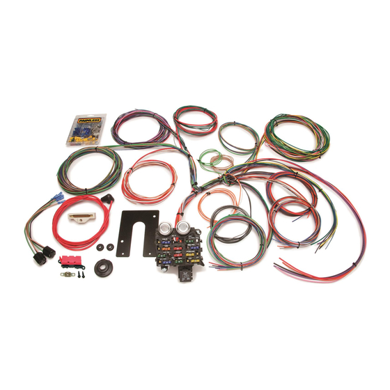
Table of Contents List of Figures..……………………………………………………………. List of Tables….…………………………………………………………… List of Diagrams………………………………………………………….. Introduction…………………………………………………………………………………………………………… 1 About These Instructions………………………………………………………………………………………… 1 Contents of the PPPI Wire Harness Kit……………………………………………………………………… 2 Tools Needed…………………………………………………………………………………………………………. 3 Pre-Installation and General Guidelines……………………………………………..……………………... 3 Wire Harness Physical Installation Instructions…………………………………………………..……… 5 Rough Installation……………………………………………………………………………………….. - Page 5 13.0 Testing the System……………………………………………………………………………………………….…..30 12.0 Wire Connection Index and Fuse Requirements……..……………………………………………….……30 12.1 Wire Connection Index…………………………….………………………………………………….…31 12.2 Fuse Requirements……………………………………………………………………………………………..…... 34 List of Figures The Painless Wire Harness Kit…………………………………………………………. MIDI-Fuse……………………………………………………………………………………... Ammeter & MIDI-Fuse…………………………………………………………………….. GM Turn Signal Connectors……………………………………………………………… Interior Lighting…………………………………………………………………………….. HEADLIGHT SECTION A…………………………………………………………………. Dimmer Switches……………………………………………………………………………...
-
Page 6: Introduction
INTRODUCTION You have purchased what we at Painless Performance believe to be the most up-to-date and easiest-to-install universal Jeep wire harness on the market. It is designed for easy installation, even if you have no electrical experience. There is enough length to the wire at all engine, dash, and tail locations to complete the installation without splicing. -
Page 7: Contents Of The Pppi Wire Harness Kit
The contents of these instructions are divided into major Sections, as follows: Introduction About These Instructions Contents of the Painless Wire Harness Kit Tools Needed Pre-Installation and General Guidelines Wire Harness Physical Installation Instructions General Electrical Systems – All Jeeps Charging and Ignition Systems - As Originally Manufactured by Jeep Charging and Ignition Systems - Jeeps with GM Engines Installed 10.0... -
Page 8: Tools Needed
Figure 3.1 Contents of the Painless Wire Harness Kit * 10105 does not come with the Turn Signal Switch Connector. TOOLS NEEDED In addition to your regular tools, you will need, at least, the following tools: Note: Use a quality tool to avoid over-crimping) Crimping Tool ( Wire Stripper Continuity Tester (test light or ohm meter) - Page 9 Familiarize yourself with the harness by locating each of the harness sections in the following list. (Whenever a particular harness section is referred to in these instructions it is shown in “all caps”: ENGINE SECTION A) Note that, according to the particular harness you have purchased, some of these sections may not be present, and some are not labeled.
-
Page 10: Wire Harness Physical Installation Instructions
Consider the following guidelines. A good exercise is to lay out the wire harness on the floor beside your Jeep and identify all the SECTIONS. You will want to route the harness through and around open areas. Inside edges provide extra protection from hazards and also provide places for tie wraps, clips, and other support. -
Page 11: Harness Attachment
6.1.3 Install the firewall grommet (early models only). Route engine and headlight group wires through the grommet and position the harness groups in the areas decided upon in Sections 5.3 and 5.4. 6.1.4 Route dash group (ACCESSORY SECTION B+, ACCESSORY SECTION SWITCHES, HEADLIGHT SECTION B, INSTRUMENT PANEL SECTION, and RADIO SECTION) upward to rear of dash and temporarily tie in place. -
Page 12: Terminal Installation And Making Connections
Terminal Installation and Making Connections Note: In the following steps you will be making the circuit connections. Before you start, you should carefully read Sections 7.0 through 11.0, as appropriate, and continually refer to Section 12.0, DOUBLE- CHECKING your routing and length calculations before cutting any wires and making connections. -
Page 13: General Electrical Systems - All Jeeps
GENERAL ELECTRICAL SYSTEMS – ALL JEEPS Generator Charging System. Use Paragraph 8.1.1. Generator to Alternator Conversion. Use Paragraph 8.1.2. Connecting an Ammeter and the Midi Fuse. See Figure 7.1. Figure 7.1 Ammeter & Midi Fuse 7.3.1 The Ammeter must be inserted IN SERIES onto the ENGINE SECTION (single 10-gauge red wire #716) that routes from the Fuse Panel to the Starter Solenoid (Starter Relay if you have a Ford or Mopar starter system). -
Page 14: Steering Column Wiring (Turn Signal & Ign. Switch Connectors)
CAUTION: BOTH AMMETER TERMINALS MUST BE ABSOLUTELY ISOLATED FROM GROUND. IF EITHER AMMETER TERMINAL COMES IN CONTACT WITH GROUND A HARNESS FIRE IS INEVITABLE. USE EXTREME CARE AND DILIGENCE IN CONNECTING AMMETERS. BE SURE YOUR AMMETER’S CURRENT (AMPS) RATING EXCEEDS THE CURRENT OUTPUT OF YOUR ALTERNATOR. -
Page 15: Interior Lighting
7.4.3 IGNITION SWITCH SECTION wire #719 (pur) has been cut and spade lugs installed on the GM keyed steering column wiring. These spade lugs are to be connected to the Neutral Safety Switch at the base of the steering column. If using a neutral safety switch on a floor shifter or in the transmission, the two purple wires with the yellow spade lugs must be connected together and the (pur) #719 needs to be routed to the neutral safety switch, cut and connected to it, then continued on to the... -
Page 16: Mopar Ignition & Turn Signal Wiring #1
1970-74 WITHOUT TILT COLUMN TURN SIGNAL CONNECTOR Mopar Designation Painless Painless Color Wire No. Color Stop Light Switch RF Turn Signal LF Turn Signal Lt.Blu RR Turn Signal LR Turn Signal Hazard Flasher Turn Flasher Horn IGNITION SWITCH CONNECTOR Ylw¹ Ignition Start Ignition Coil Accessory Fuse Panel... -
Page 17: Interior Lighting
Interior Lighting. See Figure 7.3. 7.5.1 Interior Lights are switched through the door switches and the dash-mounted headlight switch, which is usually rotated counter-clockwise to turn on. These switches apply ground to the circuit. YOU WILL NEED TO SUPPLY THESE GROUND WIRES. -
Page 18: Dimmer Switches
Note: The wire going to the fan in Figure 7.4 will be coming from the fan relay output terminal. Wire #701 (gry/wht) from the ACCESSORY SECTION SWITCHES is an activation wire for the fan relay. DO NOT TRY TO POWER THE FAN WITH THIS WIRE. 7.6.5 Connect the DIMMER SWITCH SECTION cable to its mating connector in the harness (if applicable) and your floor-mounted Dimmer Switch or column-... -
Page 19: Headlight Section B
Figure 7.7 Painless Fan Relay Kit (Part #30101) HEADLIGHT SECTION B Wiring. See Figure 7-6. 7.7.1 Connect the 6 wires of HEADLIGHT SECTION B, the Dome and Interior Light return circuit, and the Headlamp Switch Ground as shown. If you do not have a GM headlight switch, you should trace out the wires of your existing harness and connect the new harness according to Table 12-1. -
Page 20: Brake Light Switch
7.8.6 Install the #735 (red/wht) wire of the voltmeter to the driver’s side terminal and the blk wire to the passengers side terminal of the voltmeter and secure with nuts. 7.8.7 Install the #722 (lt.blu/blk) oil gauge wire to the terminal of the oil gauge and secure with nuts. -
Page 21: Charging And Ignition Systems (As Originally Manufactured By Jeep)
CHARGING AND IGNITION SYSTEMS – AS ORIGINALLY MANUFACTURED BY JEEP CAUTION: IF YOU ARE USING A HIGH AMPERAGE (65 AMPS OR HIGHER) ALTERNATOR SEE SPECIAL INSTRUCTION SHEET PP-662 INCLUDED IN THIS KIT. IF YOU DID NOT GET THIS, PLEASE CALL THE TECH LINE AT 800-423-9696 OR SEND AN E-MAIL TO TECH@PAINLESSPERFORMANCE.COM. -
Page 22: Generator To Alternator Conversion
8.1.2 Generator to Alternator Conversion You can convert your generator charging system to use an alternator and external regulator without altering or re-routing existing wires. You will need to obtain an externally regulated alternator and a compatible voltage regulator. Install the new alternator and replace the existing generator voltage regulator with the new, alternator-compatible one. -
Page 23: Motorcraft Alternator (2 Configurations)
1975 to 1978 Note: 1975-1978 could have either Motorcraft or Delco systems installed. 8.2.1 Motorcraft Alternator (2 configurations). See Figure 8.3. Note: Your Alternator may not appear exactly as represented in Figure 8.5. The circuits are wired the same way, though. Figure 8.3 Motorcraft Alternator (2 configurations) Connect the provided 6 gauge red wire to the Alternator Output lug (Bat). -
Page 24: Delco Alternator - Internal Regulator
8.2.2 Delco Alternator – Internal Regulator. See Figure 8.4. Connect ENGINE SECTION wire #714 (wht) to Alternator terminal 1. Connect ENGINE SECTION wire #795 (red) to Alternator terminal 2 Connect one end of the supplied large 6 gauge red wire to the Alternator Output lug (Bat). -
Page 25: Delco Ignition (Start/Run) System
A ballast resistor has been provided with part #10105, those with part #10106, a resistor can be obtained at your local parts store using part number RU11. -
Page 26: Prestolite Bid Ignition System (75-77)
The Ignition Coil NEGATIVE (-) terminal is connected to the Distributor. Also connect ENGINE SECTION A wire #723 (pur/wht) to the Ignition Coil NEGATIVE (-) terminal. This is the tachometer source. If you are not using a tachometer, insulate and stow wire #723. A 14-gauge wire connected from the Starter Solenoid Ignition (l) terminal to the ignition coil side of the Ballast Resistor is optional. -
Page 27: 1978 And Newer
Figure 8.6 Prestolite BID Ignition (Start/Run) System Connect ENGINE SECTION A wire #723 (pur/wht) to the Ignition Coil NEGATIVE (-) terminal. This is the tachometer source. If you are not using a tachometer, insulate and stow wire #723. 1978 and Newer 8.3.1 Delco Charging System (1979 and Newer). -
Page 28: Motorcraft Electronic Ignition (Start/Run) System
Connect ENGINE SECTION A wire #719 (pur) to the Starter Relay Start (S) terminal. Connect ENGINE SECTION A wire #720 (pnk) to one end of the existing Resistive Wire. You may replace this wire with a Ballast Resistor. Your Jeep may already have a Ballast Resistor installed. Connect the other end of the resistive wire (or Ballast Resistor) to the Ignition Coil POSITIVE (+) terminal with 14-gauge wire (you may have enough pink wire left over to accomplish this). -
Page 29: Ford Ignition Diagram (Duraspark Ii Systems)
Figure 8.8 Ford Ignition Diagram (Duraspark II Systems) Figure 8.11 Ford Switch Connectors... -
Page 30: Charging And Ignition Systems - Jeeps W/Gm Engines Installed
CHARGING AND IGNITION SYSTEMS – JEEP WITH GM ENGINES INSTALLED Note: Your Alternator may not appear exactly as represented in the Figures. The circuits are wired the same way, though. Delco Alternator (before 1969) – External Regulator. See Figure 9.1. 9.1.1 Connect ENGINE SECTION wire #795 (red) to Voltage Regulator terminal 3. -
Page 31: Ford Ignition (Start/Run) System
10.2.1 Connect the provided 6 gauge red wire to the battery stud on the Alternator. The other end of this wire will connect to the Midi fuse. 10.2.2 Connect the cut off end of the provided 6 gauge red wire from the other side of the MIDI fuse to the Starter Relay Battery terminal. -
Page 32: Charging And Ignition Systems - Jeeps W/Mopar Engines Installed
11.0 CHARGING AND IGNITION SYSTEMS – JEEP WITH MOPAR ENGINES INSTALLED 11.1 Mopar Alternator. See Figure 11.1. Note: Your Alternator may not appear exactly as represented in Figure 11.1. The circuits are wired the same way, though. Figure 11.1 Mopar Alternator 11.1.1 Mopar uses one of two kinds of voltage regulators: An electronic regulator and a mechanical one. -
Page 33: Mopar Ignition (Start/Run) System
11.1.4 Connect a 14-gauge wire from the other Alternator Field terminal (as shown in Figure 11-1) to the second terminal of the ELECTRONIC Voltage Regulator OR terminal F of the MECHANICAL Voltage Regulator. On existing Mopar harnesses, this would be a green wire. Also connect a 14-gauge wire from this terminal to chassis ground. -
Page 34: Mopar Ignition (Start/Run) System
Figure 11.2 Mopar Ignition (Start/Run) System 11.2.3 If the Neutral Safety Switch is mounted on the floor shifter, connect the Starter Relay Ground (G) terminal to chassis ground. 11.2.4 If you are using a Ballast Resistor, mount it away from other wiring and hoses. -
Page 35: Testing The System
12.0 TESTING THE SYSTEM 12.1 Use a small (10 amp or less) battery charger to power up the vehicle for circuit testing. If there is a problem anywhere, the battery charger’s low amperage and internal circuit breaker will provide circuit protection. CAUTION: IF YOU HAVE NOT YET DISCONNECTED THE BATTERY FROM THE JEEP, DO SO NOW! DO NOT CONNECT THE BATTERY CHARGER WITH THE BATTERY CONNECTED. -
Page 36: Wire Connection Index
Color Ga No. Connect to Origin Section of Origin ACCESSORY SECTION SWITCHES Gry/Wht Cooling Fan Switch Fan Relay Headlight Section A Blk/Wht A/C – Heat Switch A/C Compressor Engine Section A ACCESSORY SECTION B+ Tan(1) Cigarette Lighter B+ Fuse Panel* Fuse Panel Blk/Wht A/C –... -
Page 37: Wire Connection Index, 2 Of 3
Color Ga No. Connect to Origin Section of Origin BACKUP SECTION Lt.Grn(1) Backup Switch Fuse Panel* Fuse Panel Lt.Grn(1) Backup Switch Backup Lights Tail Section HEADLIGHT SECTION Horn B+ Horn Relay* Fuse Panel Right Front Turn Signal Turn Signal Switch Turn Signal Section Lt.Blu Left Front Turn Signal... -
Page 38: Wire Connection Index, 3 Of 3
Color Ga. No. Connect to Origin Section of Origin TURN SIGNAL SECTION Emer. Flasher Switch B+ Emer. Flasher Relay* Fuse Panel Turn Signal Sw.Flasher B+ Turn Flasher Relay* Fuse Panel Horn Switch Horn Relay* Fuse Panel Turn Signal Switch Rt.Rear Turn Signal Tail Section Turn Signal Switch Lt.Rear Turn Signal... -
Page 39: Fuse Requirements
13.2 Fuse Requirements Headlight Switch…………………………………………. 30 Emergency Flashers……………………………………… 15 Turn Signals……………………………………………… 15 Gauges……………………………………………………. 10 A/C-Heat…………………………………………………. 30 Horn……………………………………………………… 20 Wipers……………………………………………………. 15 Brake Switch…………………………………………….. Dome…………………………………………………….. Electric Fan………………………………………………. Coil……………………………………………………….. 30 Radio Ignition……………………………………………. 10 Table 12-2 Fuse Requirements... -
Page 40: Diagram 1 Engine Wiring
Diagram 1 Engine Wiring Diagram... -
Page 41: Diagram 2 Instrument Panel Section Wiring
Diagram 2 Instrument Panel Section Wiring Diagram... -
Page 42: Diagram 3 Integrated Brake Lights & Separate Turn/Brake Lights
Diagram 3 Integrated Brake Lights & Separate Turn/Brake Lights... - Page 43 Bulkhead Template The following templete is only needed for Painless part # 10106 The dimension photo on the next page shows how you can cut the bulkhead hole clean and precise using a 1 ¼” hole saw to cut 4 holes, using a jigsaw or cut off wheel to connect the outsides of the 1 ¼”...
- Page 45 Painless Performance Limited Warranty and Return Policy Chassis harnesses, fuel injection harnesses, and Trail Rocker units are covered under a lifetime warranty. All other products manufactured and/or sold by Painless Performance are warranted to the original purchaser to be free from defects in material and workmanship under normal use.
Need help?
Do you have a question about the 10106 and is the answer not in the manual?
Questions and answers