Advertisement
Quick Links
SIT Proflame II (GTMF) System
System Overview & Troubleshooting Guide
In order to troubleshoot any product it is important to understand the basic operation and
functions of that product. The following information will assist you through this process.
Kozy Heat welcomes your questions while you are at the job site. 800-253-4904
This guide is ONLY intended for professional or trained technicians.
Intermittent Pilot Ignition System
Contents
IPI System Overview
Proflame II Components
Remote Control Function
Troubleshooting
DFC Lock Outs and Reset
Remote Not Learning
Specific Issues
Multimeter Images
Wiring Diagram
Pg 2
Pg 3 - 5
Pg 6 - 8
Pg 9
Pg 10
Pg 11 - 13
Pg 14 - 18
Pg 19
1
June 2012—R1
Advertisement

Summary of Contents for kozy heat SIT Proflame II
- Page 1 In order to troubleshoot any product it is important to understand the basic operation and functions of that product. The following information will assist you through this process. Kozy Heat welcomes your questions while you are at the job site. 800-253-4904 This guide is ONLY intended for professional or trained technicians.
-
Page 2: System Overview
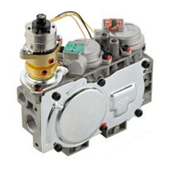
System Overview: The primary components that are included in the SIT Proflame II GTMFS System Gas Valve Integrated Fireplace Control (IFC) SIT Pilot Assembly Transmitter (remote control) (GTMF model) - Page 3 SIT Proflame GTMF Gas Valve Solenoids on Valve: EV1 (Pilot Connection Coil): Opens and closes to release gas to the pilot Orange in color furthest from step motor 5VDC and drops to 1.0VDC (test image shown on pg 16) ...
- Page 4 Integrated Fireplace Control (IFC Module) ON/OFF Switch 8 Pin Harness SW1 Button (red) Flame Sensor Step Motor Igniter Diagnostic LEDs Ground Fan Kit Power Supply Light Kit The IFC module: Acts as the “brain” of the IPI system sending commands to specific areas ...
- Page 5 Pilot Assembly Pilot Assembly is comprised of three parts Pilot Hood - Splits the flame into two for burner and flame sensor. Igniter - provides spark to the pilot hood Flame Sensor - Rectifies the pilot is lit and carries the voltage to the IFC module to stop spark- ing and allow main burner to open.
- Page 6 Remote Control Blue back lit LCD display ON /OFF Key Thermostat Key UP / DOWN Arrow Key Mode Key CPI Mode The Proflame transmitter uses radio frequency to communicate information to the receiver box located in the fireplace. The transmitter is powered by three (3) AAA batteries. As these batteries begin to wear down the blue backlight feature on the remote will deactivate indicating the batteries as beginning to lower.
- Page 7 Remote Control Button Function Blue back lit LCD display ON /OFF Key Thermostat Key UP / DOWN Arrow Key Mode Key ON/OFF Key Pressing this button one time will turn the fireplace ON in manual mode. Pressing it once more will turn the fireplace off. Note: The thermostat image on the left should read OFF for fireplace to run manually.
- Page 8 Remote Control Display Icons Key Lock To activate child lock, press the Mode Key and the Up Arrow Key at the same time. To deactivate press the same button sequence. Fahrenheit / Celsius Adjustment: With the system in the OFF position, press the Thermostat Key and the Mode Key at the same time.
- Page 9 SIT Proflame 2 IFC Module Ignition and Reset Information Ignition Sequence: Starting from OFF, press the remote power button. Approximately four seconds after it is pushed the IFC module will send spark to the pilot hood. It will spark for 60 seconds. If there is no flame ignition (rectification) during the first try for ignition, the IFC module will stop sparking for approximately 35 seconds and then it will begin sparking again.
- Page 10 Remote Not Learning to Receiver Begin Verify proper 120VAC power supply A. Remove the batteries from battery back up. B. Attempt to light continuous pilot from switch. If pilot lights or if spark is present we know power is supplied and we can proceed. If spark or pilot is not present proceed in troubleshooting steps for pilot does not light.
-
Page 11: Troubleshooting
Troubleshooting 1. Verify proper power supply throughout system Begin - See page 154for multimeter images 2. Make sure power switch is in the ON position 3. Verify wires are properly connected to IFC module 4. Make sure system is properly grounded Is the Does the 5. - Page 12 Troubleshooting 1. Verify transmitter is not powered on or in thermostat mode calling for heat. Display should say OFF next to thermometer image on display for thermo off. 2. Verify receiver switch is not in ON position 3. Ensure all electrical connections are secure based on the wiring Burner diagram lights when...
- Page 13 Troubleshooting 1. Thermostat in SMART mode will not modulate flame height 2. Check in/out pressure readings according to owner’s manual 3. Check electrical connections and inspect wiring for damage 4. Inspect main burner orifice for blockage and correct size 5. Verify receiver is receiving transmitter command by beeping Burner - If no beep, see Remote Not Learning troubleshooting flame...
- Page 14 Verifying Power Supply to IFC Module The following images are a series of tests to determine if 120V is supplied throughout the system. Figure 1.1 shows the location of the incoming power on the IFC module. Figure 1.1 Figure 1.2 displays how to test if 120VAC is supplied to the IFC module.
- Page 15 Verifying Voltage on Solenoids (EV1 and EV2) This test performed would be done if we wanted to know if the IFC module is supplying power to the Pilot solenoid (EV1) telling it to open. Multimeter would be in VDC. EV1 Solenoid One multimeter pin would be placed on the ground at the top of the valve where yellow/ green wire connect, while the other pin would...
- Page 16 Performing Ohms Reading of Valve Solenoids This test performed in Figures 3.1 and 3.2 are a continuity test of the valve solenoids. Your multimeter would need to be in the Ohms position and disconnect the wiring harness from EV1 and EV2. Using one multimeter pin on the solenoid and the other on the ground your reading should be approximately 331.4 ohms.
- Page 17 Performing Ohms Reading on Step Motor This test performed in Figure 4.1 is a continuity test of the step motor. Your multimeter would need to be in the Ohms position and disconnect wiring harness from the step motor to expose the leads. Using a multimeter place the two pins on the two leads of the connector.
- Page 18 Performing Voltage Readings on Light and Fan Kits This test performed in Figures 3.1 and 3.2 are a voltage test of the fan and light terminals on the IFC board. Your multimeter would need to be in the DC voltage position. Using one multimeter pin on the black lead and the other on the white lead your reading should be approximately 118 VDC on HI.
Need help?
Do you have a question about the SIT Proflame II and is the answer not in the manual?
Questions and answers
Got a new Proflame 2 Transmitter and successfully paired it with the fireplace. It functions perfectly, except that when I turn off the remote it displays "Er9." I read on line that this could be due to the use of lithium batteries so I replaced with alkaline batteries. Unfortunately, I still get the error message.