Table of Contents
Advertisement
Quick Links
Advertisement
Table of Contents

Subscribe to Our Youtube Channel
Related Manuals for peplink SD


Summary of Contents for peplink SD
- Page 1 Peplink SD Switch User Manual Published on October 25th, 2018...
-
Page 2: Table Of Contents
Table of Contents Switch Layout Specifications Hardware Overview Quick Start Functions Reset switch Connect Ethernet Connect SFP+ Connect to Management Port Connect to Console Port InControl Configuration Add switch to InControl Enable InControl Cloud Management Configuring VLANs Define a new VLAN Default VLAN settings InControl Device Details Port List... - Page 3 Standalone menu options > System > Time Standalone menu options > System > Schedule Establish a Scheduling Profile Standalone menu options > System > Email Notification Standalone menu options > System > Event Log Standalone menu options > System > SNMP Standalone menu options >...
-
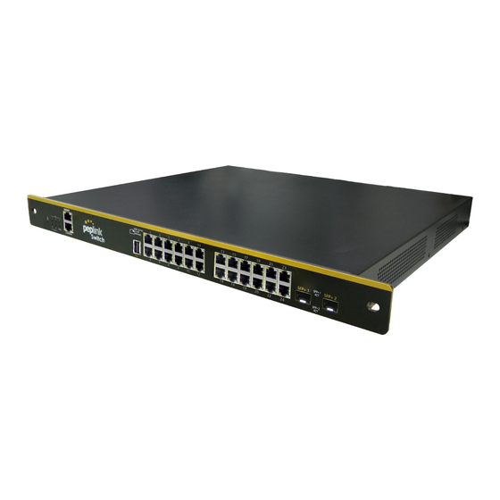
Page 4: Switch Layout
Switch Layout... -
Page 5: Specifications
Specifications SD Switch LAN Interface 24x 10/100/1000 802.3at (PoE+) enabled GbE ports, 2 x SFP+ ports Switching Capacity 88 Gbps Max. Packet Forwarding rate 66 Mbps MAC Address Table Size VLAN Groups Fiber Module 10 Gbps Power Input 2 or 3x 100V - 240V AC Input (depending on... -
Page 6: Hardware Overview
Hardware Overview Front Panel Port LED Port State Status No PoE MGMT IEEE 802.3a? Port State Status Console RJ45 1-24 poe /speed/link/act off/green/orange Link established (flashing indicates network activity) SFP+ 1-2... -
Page 7: Quick Start Functions
‘admin’ and access will be reset to HTTP) Connect Ethernet Connect an RJ45 cable from an Internet-enabled router to any RJ45 port on the Peplink SD Switch. Connect an RJ45 cable from any client device to port 1-24 of the Peplink SD Switch. -
Page 8: Connect To Console Port
(This is the default admin user login of the Peplink Balance. The admin and read-only user password can be changed at System>Admin Security.) Connect to Console Port Access the SD-Switch via this port with CLI to get the status and info of the switch. This is currently under development. InControl 2 Configuration There are two ways to configure the Peplink Switch. - Page 9 2: Connect an active ethernet connection to one of the numbered switch ports 1 to 24. 3: The Switch will show online in InControl 2 (the marker on the map will change from red to green).
-
Page 10: Enable Incontrol Cloud Management
Enable InControl 2 Cloud Management InControl 2 management needs to be enabled to allow the Peplink Switch to be configured through InControl 2. This setting is enabled by default. The settings can be changed in the local web interface of the Switch. -
Page 11: Configuring Vlans
Navigate to S ystem > InControl , and then click the “ A llow InControl Management ” button Click the “ A pply Changes ” text on the top-right corner to save your changes. Configuring VLANs From the available InControl Group settings, the ... - Page 12 Switch to InControl. Important: The Peplink switch is a Layer 2 switch. Any routing options that are shown in the VLAN settings (like Inter-VLAN routing) do NOT apply to the switch. These settings are only applied to Peplink Balance and Pepwave Max routers in the same InControl group supporting that option.
-
Page 13: Define A New Vlan
Define a new VLAN To add a new VLAN click on the “Add VLAN Network” button in the Network settings > VLAN Networks section of InControl. -
Page 14: Default Vlan Settings
Enter the desired parameters and click “Save” to apply the settings. Default VLAN Settings... -
Page 15: Incontrol Device Details
By default, the default VLAN ID is set to 1. When any untagged frames or frames tagged as 1 enter into any Peplink SD Switch's trunk ports which are configured with Accept Frame Type option set to "All", the frames will be assigned to VLAN 1. -
Page 17: Port List
Device name, tags, location, and notes can be changed through the “Edit” link: Select the Save button on the bottom of this page to save the settings and return to the device details page. Or Cancel to discard changes and return to the Device Settings page. Port List The Port List shows the available switch ports and their status. - Page 18 Port Icons Glossary port down port up - PoE not drawing power port up -PoE drawing power port up - link to InControl2...
-
Page 19: Port Details And Configuration
Port Details and Configuration Additional port details appear when clicking on an individual port from the device details page. Single or multiple ports can be selected and edited. Configurable options (port 1 - 24) Enable / disable Enable or disable the switch port PoE enable / disable Enable or disable PoE on the port... -
Page 20: Port List
Speed Select ports speeds 10 or 100 Mbps half or full Duplex or 1 Gbps full Duplex. Port Type Trunk or Access port VLAN All or CUSTOM (select 1 or more existing VLANs) Accept Frame Type Frame Types the port accepts (VLAN tagged only, or All) RSTP Enable or disable RSTP (Rapid Spanning... - Page 21 This will show (or hide) a table showing port details.
-
Page 22: Lacp - Link Aggregation
LACP - Link Aggregation IEEE 802.3ad link aggregation enables you to group Ethernet interfaces to form a single link layer interface, also known as a link aggregation group (LAG). The maximum interfaces per LAG is 24. The advantages of link aggregation in contrast with connections using an individual port include: ●... -
Page 23: Incontrol Reports
InControl Reports Search through the SD Switch event logs, filter results by topic, time, client and details. Download the event log in .csv format. InControl Clients View client details from client devices connected to the SD Switch. -
Page 24: Incontrol Settings
InControl group and Device Tools. Settings > Remote Web Admin Remote Web Admin opens the web admin interface of the SD Switch in a separate tab. Settings > Firmware Management... -
Page 25: Standalone Configuration
Standalone Configuration When configuring the Switch in Stand Alone mode, Incontrol Management needs to be disabled. After connecting to the management port and logging on to the Web Interface of the Switch, browse to S ystem > InControl a nd uncheck the “ Allow InControl Management” option. -
Page 26: Standalone Menu Options > Dashboard
When this box is unchecked, your device will not be allowed to communicate with InControl. Standalone menu options > Dashboard... - Page 27 The Device Details page shows the following detailed information about the the SD-Switch. Port Overview Firmware Fan Speed Management port IP Uptime Temperature Management VLAN IP CPU Load AC source status Model Power Consumption Portlist When hovering over a port, a popup window with port details displays the following information:...
-
Page 28: Standalone Menu Options > Configure > Network Settings
Standalone menu options > Configure > Network Settings VLANs are configured in the C onfigure > Network Settings s ection of the Switch web interface. To define a new VLAN select the “ N ew LAN ” option. On the following screen, enter your desired parameters. -
Page 29: Standalone Menu Options > Configure > Interfaces > Switch Ports
Click “ S ave ” and then click the “ A pply Changes ” button on the top-right. Standalone menu options > Configure > Interfaces > Switch Ports For each port, you can set PoE scheduling, port type (Trunk and Access), as well as the VLAN which they belong to. - Page 30 On the following screen, enter your desired parameters. Configurable settings are: Port Name Enable /Disable Port enable , disable or add a schedule Port Speed Port Type Trunk or Access VLAN Networks select VLAN tags RSTP enable or disable Rapid Spanning Tree Protocol...
-
Page 31: Lacp (802.3Ad) Configuration
After making changes click “ S ave ” and then click the “ A pply Changes ” button on the top-right corner of the interface. LACP (802.3ad) Configuration LACP is part of the IEEE specification 802.3ad and allows you to bundle several physical ports to form a single logical channel. -
Page 32: Standalone Menu Options > System > Admin Security
Standalone menu options > System > Admin Security The Admin Security page allows you to configure the following settings: Switch Name Switch hostname Admin user name Admin Password Read-only username User password Web Session Timeout A web login session will be logged out automatically when it has been idle longer than the Web Session Timeout. - Page 33 0 hours 0 minutes signifies an unlimited session time. This setting should be used only in special situations as it will lower the system security level if users do not logout before closing the browser. The default setting is 4 hours 0 minutes Security HTTP / HTTPS sessions or both are allowed to connect to the web admin interface.
-
Page 34: Standalone Menu Options > System > Firmware
You can either click the C heck for Firmware button to contact the firmware server to check for new firmware or manually upgrade the SD-Switch with a downloaded firmware file. Firmware can be downloaded from the Peplink website:... -
Page 35: Standalone Menu Options > System > Time
Standalone menu options > System > Time This section allows you to select a Time Zone and configure a Time Server. Standalone menu options > System > Schedule Schedules can be created and applied to port PoE settings. Establish a Scheduling Profile To Define a schedule, navigate to ... - Page 36 The following screen will appear. Enter the desired name and click the grid to define your schedule and then click “ S ave ” . Click the “ A pply Changes ” text on the top-right corner to save your changes.
-
Page 37: Standalone Menu Options > System > Email Notification
Standalone menu options > System > Email Notification The feature Email Notification allows email to be sent to the listed recipient email addresses when the following events take place: ● Email notification test ● A new firmware version is available ●... -
Page 38: Standalone Menu Options > System > Event Log
The default Syslog port used and configured is UDP 514; this is an option that can be configured to use a different port. Standalone menu options > System > SNMP SNMP or Simple Network Management Protocol is an open standard that can be used to collect information about the Peplink Balance unit. - Page 39 SNMP Settings SNMP Device Name This field shows the router name defined at System>Admin Security SNMP Port This option specifies the port which SNMP will use. The default port is 161. SNMPv1 This option allows you to enable SNMP version 1. SNMPv2 This option allows you to enable SNMP version 2.
-
Page 40: Standalone Menu Options > System > Incontrol
Standalone menu options > System > InControl InControl is a cloud-based service which allows you to manage all of your Peplink and Pepwave devices with one unified system. With it, you can generate reports, gather statistics, and configure your devices automatically. All of this is now possible with... -
Page 41: Standalone Menu Options > System > Configuration
Standalone menu options > System > Configuration Backing up Peplink Balance settings immediately after successful completion of initial setup is strongly recommended. The functionality to download and upload Peplink Balance settings is found at S ystem>Configuration . -
Page 42: Standalone Menu Options > System > Reboot
This page provides a reboot button for restarting the system. For maximum reliability, the Peplink Balance Series can equip with two copies of firmware, and each copy can be a different version. You can select the firmware version you would like to reboot the device with. -
Page 43: Ping
Standalone menu options > System > Tools Ping The ping test tool sends pings through a specified Ethernet interface or a SpeedFusion VPN connection. You can specify the number of pings in the field N umber of times to a maximum number of 10 times. -
Page 44: Wake-On-Lan
The traceroute test tool traces the routing path to the destination through a particular Ethernet interface or a SpeedFusion connection. A system administrator can use the traceroute utility to analyze the connection path of a LAN/WAN connection. Wake-on-LAN Wake-on-LAN is a technology that allows a network professional to remotely power on a computer or to wake it up from sleep mode (if this is supported by the client device)... - Page 45 Security . Model This shows the model name of the device. Hardware Revision This shows the hardware version of this device. Serial Number This shows the serial number of this device. Firmware This shows the firmware version this device is currently running.
-
Page 46: Standalone Menu Options > Status > Client List
Assign a name to a client by clicking on the N ame field of the client and inputting a name. Standalone menu options > Status > Event Log The log section displays a list of events that has taken place on the SD-Switch. Check A uto Refresh to refresh log entries automatically. - Page 47 Click the C lear Log button to clear the log. Additional troubleshooting resources Peplink Knowledgebase: https://forum.peplink.com/c/knowledgebase Peplink Community Forums: h ttps://forum.peplink.com/ Contact Us: Sales http://www.peplink.com/contact/sales/ Support http://www.peplink.com/contact/ Certified Peplink Partner http://www.peplink.com/partners/channel-partner-program/...
Need help?
Do you have a question about the SD and is the answer not in the manual?
Questions and answers