Advertisement
Quick Links
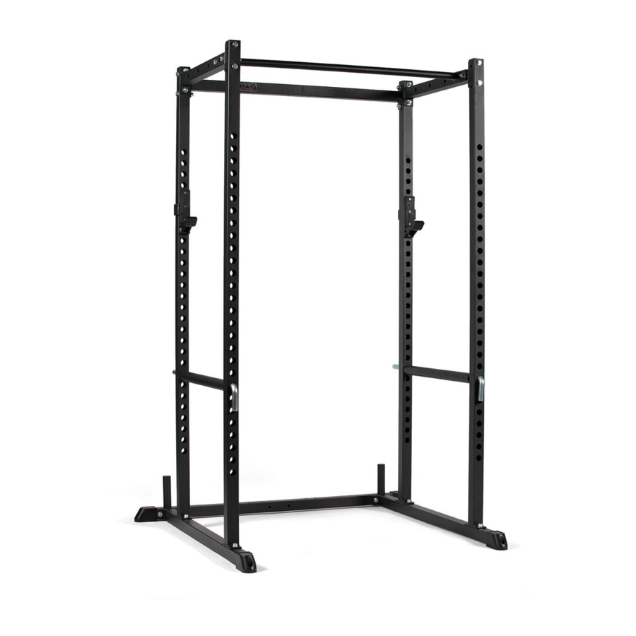
POWER RACK
DIAGRAM NO.
PACKAGE NUMBER
1
2
3
4
5
6
7
8
9
10
11
12
13
14
PART NUMBER
P400100-1
1
Jhook
2
P400100-3
2
P400100-4
2
P400100-5
2
P400100-6
1
P400100-7
1
P400100-8
1
P400100-9
1
P400100-10
1
P400100-11
1
P400100-12
1
P400100-13
1
P400100-14
1
DESCRIPTION
(PN)
Back Leg
Jhook
Side Leg
Pull-up Bar
Spotter Bar
Molded Feet
Upper Side Support Brace
Upper Rear Support Brace
Upright Poles
Plastic Square Cap
Plastic Round Cap
Square Bolt M12*75
Nylon Lock Nut M12
Hex Bolt M12x80
QTY
1
2
2
1
2
4
2
1
4
4
2
8
28
20
MPN: PWR1-PWR2
SKU: 400100
UPC: 765857424125
Advertisement

Summary of Contents for Titan T-2 Series
- Page 1 POWER RACK DIAGRAM NO. PACKAGE NUMBER PART NUMBER DESCRIPTION (PN) P400100-1 Back Leg Jhook Jhook P400100-3 Side Leg P400100-4 Pull-up Bar P400100-5 Spotter Bar P400100-6 Molded Feet P400100-7 Upper Side Support Brace P400100-8 Upper Rear Support Brace P400100-9 Upright Poles P400100-10 Plastic Square Cap P400100-11...
- Page 2 PACKAGE 1 [PWR1] PACKAGE 2 [PWR2] (1) Back Leg 1 PC (2) Jhooks 2 PCS (6) Molded Feet 4 PCS (3) Side Leg 2 PCS (7) Upper Side Support Brace 2 PCS (4) Pull-up Bar 1 PCS (8) Upper Rear Support Brace 1 PCS (5) Spotter Bar 2 PCS...
- Page 3 STEP 1 Bolt the two (3) Side Legs to the (1) Back Leg using the (15) Hex Bolt M12x80. (1) Back Leg (3) Side Legs STEP 2 Attach the four (9) Upright Poles to the (3) Side Legs. Use the (12) Square Bolts M12x75, insert them from the bottom up.
- Page 4 (7) Upper Side Support Brace (8) Upper Rear Support Brace STEP 4 Attach the (8) Upper Rear Support Brace bar and the (7) Upper Side Support Brace to rear (9) Upright Poles, using the (15) Hex-bolt M12x80. (9) Upright Poles (7) Upper Side Support Brace STEP 5 Attach the (4) Pull-up bar to (7) Upper Side Support Brace...
Need help?
Do you have a question about the T-2 Series and is the answer not in the manual?
Questions and answers