Table of Contents
Advertisement
Quick Links
Marine Electrical Products
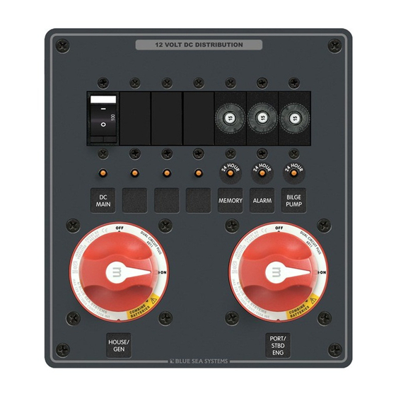
Triple Battery Main Distribution Panel
Two Dual Circuit Plus
PN 8689/8693
Features
• Power distribution, switching, and circuit protection combined in one panel
• Configurable to suit specific needs of individual boat owners
• Dual Circuit Plus
Battery Switch: m-Series (8689) or e-Series (8693)
TM
• Three (8689) or four (8693) 15A thermal circuit breakers provide 24-hour
circuit protection
• Each circuit contains circuit labels and LED indicator lights that provide
circuit status
• Blank slots to accommodate additional circuit breakers or switches
Panel Specifications
Material:
0.125" 5052-H32 Aluminum Alloy
Primary Finish:
Chemical Treatment per MIL SPEC C-5541C
Final Panel Finish:
Graphite color 2 part textured Polyurethane
Maximum Voltage Rating:
24V DC
House Amperage Rating:
100A Max (on installed circuit)
Switch Amperage Ratings:
Continuous: 8689-300A, 8693-350A
Intermittent (5 min.): 8689-450A, 8693-525A
Cranking (10 sec.): 8689-1,000A, 8693-1,000A
PN
Dimensions:
8689
8693
Mounting Centers:
8689
8693
Switch Terminal Studs:
3/8"-16 (accepts M10 terminal)
Torque:
140 in-lbs.
Blue Sea Systems Inc.
425 Sequoia Drive
Bellingham, WA 98226 USA
How it works
The Dual Circuit Plus
Battery Switch turns the house and start batteries
™
on at the same time, but isolates them from each other. Battery isolation
protects the start battery from being discharged from the many house loads
like refrigerators, stereos, and lights, preserving it for starting the engine.
Battery isolation also protects sensitive electronics from voltage spikes and
sags that may occur during engine starting. The Dual Circuit Plus
Switch simplifies battery switch operation--it performs the same operation
as three ON/OFF battery switches. The engine and house batteries are
turned ON at the same time when the boat is boarded and OFF when the
boat is not in use. This minimizes the opportunity for error. In an emergency
requiring that both batteries be combined—e.g., a discharged start battery—
the operator simply turns the switch knob to the COMBINE BATTERIES
position.
The Dual Circuit Plus
Battery Switch automates the charging of two battery
™
banks when coupled with an Automatic Charge Relay (PN 7610 or PN
9112). This combination creates a complete battery management system
of isolated battery circuits, emergency cross connect (emergency parallel)
functions, and automated charge management.
Battery Switches
™
Inches
Millimeters
7.25 x 8.00
184.15 x 203.20
10.50 x 8.00
266.70 x 203.20
6.42 x 7.17
163.07 x 182.12
9.67 x 7.17
245.62 x 182.12
Phone (360) 738-8230
Fax (360) 734-4195
www.bluesea.com
6346 Rev. 005
Battery
™
WARNING
]
If the installer is not knowledgeable about electrical systems,
consult an electrical professional.
]
If either the panel front or back is to be exposed to water it must be
protected with a waterproof shield.
]
Standard Blue Sea Systems battery management panels are ignition
protected as shipped.
]
Custom panels are ignition protected when supplied with ignition
protected circuit breakers.
]
The main positive connection must be disconnected at the battery post
to avoid the possibility of a short circuit during the installation of
this distribution panel.
Guarantee:
Blue Sea Systems stands behind its products for as long as you own
them. Find detailed information at www.bluesea.com/about. For
customer service, call 800-222-7617.
Applicable Standards
• American Boat and Yacht Council (ABYC) Standards and
Recommended Practices for Small Craft sections: E-1, E-3, E-11.
• United States Coast Guard 33 CFR Sub Part 1, Electrical Systems.
• National Fire Protection Agency (NFPA) 302
Useful Reference Books
• Calder, Nigel (2005). Boatowner's Mechanical and Electrical Manual
(3d ed). Camden, ME: International Marine / McGraw-Hill.
• Wing, Charlie (2006). Boatowner's Illustrated Electrical Handbook
(2d ed). Camden, ME: International Marine / McGraw-Hill.
Other Innovative Products from Blue Sea Systems
• 360 Panel System
• Battery management solutions
• AC and DC circuit protection devices
• WeatherDeck™ waterproof panels
• BusBars, fuses, and fuse blocks
• Analog and digital meters
Installation
1. Disconnect all DC power
To eliminate the possibility of a short circuit while installing the panel,
disconnect the main positive cable from all batteries.
2. Select mounting location and cut opening
Select a mounting location that is protected from water on the panel front
and back and is not in an area where flammable vapors from propane,
gas or lead acid batteries accumulate.
Using the panel template provided, make a cut out in the mounting
surface where the panel is to be mounted. Do not fasten the panel to the
mounting surface.
3. Install LED negative feed wire
Use a 16 AWG wire to connect the LED negative feed (Yellow) wires to a
DC negative bus.
4. Electrical Connections
Battery cable terminals must be attached under battery switch stud nut
and lock washer. The electrical connection illustration is general in
nature and is not meant to be a guide for the wiring of any specific
vessel. There are many possible wiring configurations. Consult your
marine electrical professional for the wiring system applicable to
your boat.
Make appropriate adjustments to the wiring diagram to suit your specific
installation and equipment. Fusing may be appropriate in several of the
lines depending on the proximity of components, conductor sheathing,
and the conductivity of the surrounding structure. Consult the Wire
Sizing Chart to determine the appropriate wire sizes.
5. Apply Labels and Mount Panel
Apply a label to each of the circuits from the label sheet provided.
Additional labels are available from Blue Sea Systems. Fasten the
panel to the mounting surface using the screws provided.
Advertisement
Table of Contents

Subscribe to Our Youtube Channel
Related Manuals for Blue Sea Systems 8689


Summary of Contents for Blue Sea Systems 8689
- Page 1 • Dual Circuit Plus Battery Switch: m-Series (8689) or e-Series (8693) protected circuit breakers. • Three (8689) or four (8693) 15A thermal circuit breakers provide 24-hour The main positive connection must be disconnected at the battery post circuit protection to avoid the possibility of a short circuit during the installation of •...
- Page 2 1250 5000 2500 Blue Sea Systems Battery Management Panels contain thermal (push button reset) circuit breakers rated at 15A. These circuit breakers are suitable for 24-hour circuits connected directly to 12V or 24V battery banks with CCA capacities up to and including 650 CCA.
Need help?
Do you have a question about the 8689 and is the answer not in the manual?
Questions and answers