Table of Contents
Advertisement
Quick Links
* Requires the MGL Avionics magnetic field or active current shunt (sold separately)
Blaze INFO-2
Information Display
Operating Manual – English 1.00
G-force meter
UTC and local time display
Slip indicator
Battery Voltage, *Current and Charge display
OAT display
Flight Timer & Flight log
Stopwatch
Countdown Timer
Alarm
Advertisement
Table of Contents

Subscribe to Our Youtube Channel
Related Manuals for MGL Avionics Blaze INFO-2

Summary of Contents for MGL Avionics Blaze INFO-2
- Page 1 Operating Manual – English 1.00 G-force meter UTC and local time display Slip indicator Battery Voltage, *Current and Charge display OAT display Flight Timer & Flight log Stopwatch Countdown Timer Alarm * Requires the MGL Avionics magnetic field or active current shunt (sold separately)
- Page 2 12V and 24V aircraft and can measure voltages up to 30V DC. The INFO-2 uses the MGL Avionics magnetic field or active current shunt to measure the aircrafts current load. The INFO-2 contains a programmable low/high voltage alarm to automatically detect bad batteries and alternator failures. The maximum and minimum voltage reached is also recorded in permanent memory.
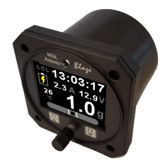
- Page 3 Wide input supply voltage range of 8 to 30V DC with built in voltage reversal and over voltage protection for harsh electrical environments • 1 year limited warranty * Requires the MGL Avionics magnetic field or active current shunt (sold separately) 2 Layout Ambient light sensor Sunlight readable color graphic display: 3 1/8”...
-
Page 4: Main Displays
Blaze INFO-2 Operating Manual Page 4 3 Main Displays The INFO-2 has various display screens depending on the mode selected. The local time, G-force, Slip (if enabled) and OAT (if enabled) is shown on all of the main display screens. -
Page 5: Flight Timer
Blaze INFO-2 Operating Manual Page 5 3.2 Flight Timer Local time Local time label Flight time Flight timer label G-force display Press the F1 key to Start/Stop Slip Indicator the flight timer. The F1 key is (if enabled) only active if the flight timer is set... -
Page 6: Countdown Timer
Blaze INFO-2 Operating Manual Page 6 3.3 Stopwatch The stopwatch can be started and stopped at any time and reset to zero. Local time Local time label Stopwatch time Indicates stopwatch is running G-force display Stopwatch label Press the F1 key to... - Page 7 Blaze INFO-2 Operating Manual Page 7 Slip Indicator disabled Slip Indicator & OAT disabled 3.5 Alarm Local time Local time label Indicates alarm is on Alarm time Alarm label G-force display OAT display (if enabled) Press the F2 key to...
- Page 8 Blaze INFO-2 Operating Manual Page 8 3.6 Battery Voltage / Current display Both the battery voltage and current can be displayed. If the current measurement is disabled then the battery voltage will be shown with a bargraph. Dual Mode (Both battery voltage and current shown)
- Page 9 Blaze INFO-2 Operating Manual Page 9 3.7 OAT (Outside Air Temperature) The OAT display is shown on all the main displays. The OAT display can be disabled in the menu system. OAT display OAT unit 3.8 G-force The G-force display is shown on all the main displays. The cycle counter and the maximum/minimum values are only shown on certain displays.
-
Page 10: Exiting The Menu System
Blaze INFO-2 Operating Manual Page 10 4 Menu System Press the rotary control button during the normal display mode to enter the menu system. Use the rotary control to navigate through the menu system. 4.1 Exiting the menu system Press the F1 button to exit the menu system when the “EXIT” soft key is shown. All changes made during navigation of the menu system will be saved in non-volatile memory upon exiting. - Page 11 Blaze INFO-2 Operating Manual Page 11 4.2 Flight Timer View Flight Log: Use the rotary control to view the next flight log entry. Erase Flight Log: Use this function to erase the flight log stored in the INFO-2. FT Display: Select to enable or disable the flight timer display.
- Page 12 Blaze INFO-2 Operating Manual Page 12 4.3 G-Force Setup Pos Alarm: This enables or disables the positive G-force alarm. Pos Alarm: Enter the G-force threshold for when the positive alarm must be activated. Any G-force above this value will activate the alarm.
-
Page 13: Time Setup
Blaze INFO-2 Operating Manual Page 13 4.4 Time Setup Set UTC Time: This function is used to set the internal real time clock. The time to be entered must be UTC in order for the system to operate correctly. Do not enter local time (unless it is the same as UTC). - Page 14 Blaze INFO-2 Operating Manual Page 14 4.5 Volts Setup Display Max: Select the maximum value that you want the volts bargraph to show. This can give you increased display resolution. The bargraph is only shown if the current display is disabled.
- Page 15 Blaze INFO-2 Operating Manual Page 15 4.6 Current Setup (MGL Avionics magnetic field or active shunt required) Current Disp: Select to enable or disable the current display. High Alarm: This enables or disables the current high alarm. High Alarm: Enter the current threshold for when the high alarm must be activated. Any current above this value will activate the alarm.
- Page 16 Blaze INFO-2 Operating Manual Page 16 Zero Sensor: Select this function to indicate to the INFO-2 that zero current is flowing through the MGL current sensor. This is best done with the MGL current sensor disconnected from the main current supplying conductor.
- Page 17 Blaze INFO-2 Operating Manual Page 17 4.7 OAT (Outside Air Temperature) Setup OAT Display: Select to enable or disable the OAT display. Temp Unit: Select whether you want the OAT to be displayed in degrees Celsius (ºC) or in degrees Fahrenheit (ºF).
- Page 18 Blaze INFO-2 Operating Manual Page 18 4.8 Slip Setup Slip Display: Select if you would like to enable the slip indicator to be shown on the bottom of the display. Slip Sense: Select if you want the slip to have a high sensitivity or a low sensitivity setting.
- Page 19 Blaze INFO-2 Operating Manual Page 19 4.9 MISC Setup (Miscellaneous Setup) Backlight: Select manual or automatic backlight control. Use the rotary control in manual mode to adjust the backlight brightness. Allow 3 seconds for the display to adjust to the ambient lighting conditions when using the automatic backlight mode.
-
Page 20: Loading Factory Default Settings
Blaze INFO-2 Operating Manual Page 20 Default Settings: Select this menu option to reset all the settings to factory defaults. 4.10 ADC Values This menu displays the ADC values from the various sensors. 5 Loading factory default settings Press and hold the F1/Up button and rotary control during power up to load the pre- programmed factory default settings. -
Page 21: Specifications
100000 write cycles Voltage measurement range Up to 32Vdc Voltage resolution 0.1V Current shunts supported MGL Avionics magnetic field or MGL Avionics active current shunt G-force range +-16g typical OAT Temperature Sender type Semiconductor LM335 (ON Semiconductor) Internal battery type... -
Page 22: Installation
Blaze INFO-2 Operating Manual Page 22 10 Installation 10.1 Connection Diagram The use of an external 1A fuse is recommended. Connect the supply terminals to your aircrafts power supply. The INFO- 2 can be used on both 12V and 24V without the use of any pre-regulators. Ensure that the supply voltage will not drop... -
Page 23: Cable Connections
Blaze INFO-2 Operating Manual Page 23 10.2 Cable connections Main connector (D15HD connector: Unit Female, Cable Male) D15HD Pin Color Function 8-30Vdc power via power switch / circuit breaker and fuse. Black Ground. Connect the ground to the engine block, and the engine block to the battery negative. - Page 24 IMPORTANT NOTICE: You must make your own determination if the products sold by MGL Avionics are safe and effective for your intended applications. MGL Avionics makes no representations or warranties as to either the suitability of any of the products we sell as to your particular application or the compatibility of any of the products we sell with other products you may buy from us or anywhere else, and we disclaim any warranties or representations that may otherwise arise by law.
Need help?
Do you have a question about the Blaze INFO-2 and is the answer not in the manual?
Questions and answers