Advertisement
Quick Links
READ COMPLETE SAFETY INSTRUCTIONS, PRE-INSTALLATION SETUP AND CHECKOUT PROCEDURE
FOR BYPASS HUMIDIFIER AND INSTALLATION / TEMPLATE INSTRUCTIONS BEFORE STARTING
This product must be installed by a qualified heating and air conditioning contractor. Failure to do so could result in serious injury from electrical shock.
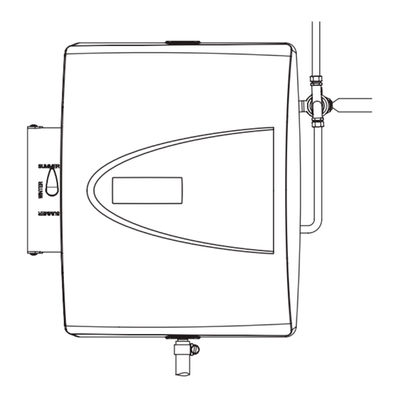
BYPASS HUMIDIFIER MODEL *HUMD300A
WARNING
ELECTRICAL SHOCK HAZARD.
1.
Disconnect electrical power to the
furnace before starting installation.
Failure to do so could result in
serious injury from electrical shock.
SHARP EDGES HAZARD.
2.
Sharp
edges may cause serious injury from
cuts. Use care when making plenum
openings and handling ductwork.
Use personal protective equipment
when installing HVAC equipment.
RISK OF SCALDING.
3.
Water
temperature over 125°F can cause
severe burns and scald instantly.
Shut off the hot water supply before
disconnecting or tapping into any
hot water supply line.
WIRING DIAGRAM
(SEE "INSTALLER'S GUIDE / AUTOMATIC HUMIDIFIER CONTROL, FORM #18-CH31D1-2"
FOR DETAILED WIRING INSTRUCTIONS)
NOTE: FOR COMMUNICATING SYSTEM WIRING DIAGRAMS,
SEE ENCLOSED INSTALLER'S GUIDE, FORM 18-HE87D1-1.
NOTE
VERIFY THAT SWITCH IS IN
THE "BYPASS" POSITION.
24 VAC FURNACE ACCESSORY TERMINALS
(10 VA MINIMUM) OR
24 VAC TRANSFORMER (10 VA MINIMUM)
IMPORTANT
DO NOT WIRE TRANSFORMER
INTO FURNACE BLOWER CIRCUIT.
SHUT-OFF
(SADDLE VALVE)
WATER SUPPLY
YELLOW 24 V
SOLENOID
VALVE WIRES
90-1132
CONNECT DRAIN LINE HERE
Trane
6200 Troup Highway
Tyler, TX 75711-9010
ATTENTION INSTALLER:
This product must be installed in compliance with all local, state and federal codes.
RISK OF PROPERTY AND EQUIPMENT DAMAGE.
1. Do not install in attic or crawl areas.
2. Do not install humidifier where freezing temperatures
could occur. The water line could freeze and crack
causing water damage to the home.
3. Do not install humidifier or bypass connection on the
furnace cabinet.
4. Do not install humidifier or bypass connection on a
plenum face where the blanked off ends of the cooling
coil will restrict air movement through the humidifier.
5. Do not set humidity level above recommended or to
recommended level if condensation exists on inside
windows of any unheated space, as condensation
damage may result. Excess humidity can cause
moisture accumulation which can allow the possibility
for mold growth in the home.
R
C
H
ODT
24V
NOTE
FOR INSTALLATION IN MANUAL MODE, REPLACE
OUTDOOR TEMPERATURE SENSOR WITH PLASTIC
RESISTOR CASE AND ATTACH MANUAL FACE
PLATE. SEE "INSTALLER'S GUIDE / AUTOMATIC
HUMIDIFIER CONTROL, FORM #18-CH31D1-1"
INCLUDED WITH EACH HUMIDIFIER.
IMPORTANT
NOTE: THE INTEGRATED FURNACE CONTROL HAS
OPTIONAL ACCESSORY CONNECTIONS FOR THE
HUMIDIFIER. SEE THE FURNACE INSTALLER'S GUIDE
FOR THE SCHEMATIC DIAGRAM OF THE FURNACE
AND THE FIELD WIRING DIAGRAM FOR THE
OPTIONAL ACCESSORIES.
IMPORTANT
USE THE 120 VAC POWER SOURCE ON THE INTEGRATED
FURNACE CONTROL HUMIDIFIER ACCESSORY
TERMINALS MARKED HUM-H, HUM-N TO POWER THE
HUMIDIFIER CONTROL TRANSFORMER.
TEMPLATE MUST BE LEVEL
TOP
CAUTION
6. Do not connect humidifier transformer to
blower motor wiring. Premature component
failure may result.
7. When installing Humidifier Control on
downflow furnace, ensure blower continues to
run after a heat call is satisfied to eliminate
high temperatures from damaging the Control.
8. Do not install humidifier where water pressure
exceeds 125 psi, since damage to the
humidifier may result. Follow codes in effect
concerning pressure reduction.
9. Do not install humidifier on the supply plenum
where static pressure exceeds 0.2" W.C.
INSTALLATION OPTIONS
The humidifier can be installed on either the supply or return plenum of a forced
air handling system and is easily reversible for installation with right hand or
left hand bypass duct connections. The humidifier dimensions and serviceability
must be considered when selecting the best location for the humidifier.
RETURN
AIR
NORTH, EAST
OR WEST SIDE
OF HOME
HUMIDIFIER
OUTDOOR
TEMPERATURE
SENSOR
ABOVE EXPECTED
SNOW LINE
Upflow Furnace
OPTION "A" REAR OF FURNACE
OR REAR MOUNT
RETURN
AIR
90-1105
Horizontal Furnace
*May be "A" or "T"
SPECIFICATIONS
HUMIDIFIER DIMENSIONS
Width
(including solenoid valve):
Height
(including drain spud):
Depth
BYPASS DUCT OPENING
6" diameter
PLENUM OPENING
9
7
⁄
"W x 12
8
WATER FEED RATE
3 gph
ELECTRICAL DATA
24 VAC-60 Hz, 0.5 AMP
SUPPLY
FLUE
AIR
RETURN
AIR
FLUE
COOLING
COIL
Upflow Furnace
OPTION "B" FRONT OF FURNACE
OR FRONT MOUNT
RETURN AIR
HUMIDIFIER
COOLING COIL
HUMIDIFIER
SUPPLY
AIR
SUPPLY AIR
Downflow Furnace
15
3
⁄
Ó
8
15
⁄
"
3
4
10
1
⁄
"
:
4
5
⁄
"H
8
SUPPLY
AIR
HUMIDIFIER
COOLING
COIL
OPTIONAL FLUE
NOT ALL MODELS
COOLING COIL
Advertisement

Related Manuals for Trane HUMD300A


Summary of Contents for Trane HUMD300A
-
Page 1: Specifications
This product must be installed by a qualified heating and air conditioning contractor. Failure to do so could result in serious injury from electrical shock. This product must be installed in compliance with all local, state and federal codes. BYPASS HUMIDIFIER MODEL *HUMD300A *May be “A” or “T”... -
Page 2: Parts List
– TOP – READ REVERSE SIDE FIRST! READ REVERSE SIDE FIRST! READ COMPLETE SAFETY INSTRUCTIONS AND INSTALLATION TEMPLATE BEFORE STARTING Figure 1 Figure 2 Figure 3 FURNISHED ITEMS Built-in bypass damper 24 VAC Transformer Automatic Humidifier Control Automatic Humidifier Control Installation Sheet Saddle valve Humidifier Installation Template...
Need help?
Do you have a question about the HUMD300A and is the answer not in the manual?
Questions and answers