Table of Contents
Advertisement
Advertisement
Table of Contents

Summary of Contents for Logosol E37
- Page 1 USER MANUAL Ref. no. 0458-395-0552 OPTIONAL ATTACHMENT ELECTRIC FEED UNIT...
- Page 2 It would be a pity if that were not utilised. We hope you get a lot of satisfaction from the use of your new LOGOSOL product. Bengt-Olov Byström Founder and chairman, Logosol in Härnösand, Sweden...
-
Page 3: Table Of Contents
TABLE OF CONTENTS Safety instructions Description of the equipment Components: on delivery Components: electric feed unit Components: support leg Components: wire tensioner Tools required Assembly: support legs Assembly: wire tensioner Assembly: electric feed unit Assembly: wire and wire attachment Adjustment: support legs Adjustment: wire tensioner Adjustment: electric feed unit Control panel... -
Page 4: Safety Instructions
• VOnly add extra equipment to the product that is made by LOGOSOL or that is specifically approved by LOGOSOL for the purpose. Other equipment can cause accidents and should not be used. -
Page 5: Description Of The Equipment
With the LOGOSOL Electric Feed Unit the guide bar and the chains will last longer, and it is easy to maintain optimum sawing speed. -
Page 6: Components: On Delivery
COMPONENTS: ON DELILVERY The product comes in 4 boxes consisting of 1 wire tensioner, 2 support legs, and 1 electric feed unit. Check that all of these boxes are included in the shipment when receiving it. Electric feed unit 6600-000-3035 (400V) 6600-000-3040 (230V) Support legs Wire tensioner... -
Page 7: Components: Electric Feed Unit
OPTIONAL ATTACHMENT ELECTRIC FEED UNIT COMPONENTS: ELECTRIC FEED UNIT Contents of the box. Electric feed unit Bolt bag User manual Electric feed unit 6600-000-3035 (400V) 6600-000-3040 (230V) -
Page 8: Components: Support Leg
COMPONENTS: SUPPORT LEG Contents of the box. Assembly instructions Support leg, top on page 12 Support leg, bottom Bolt bag Support leg 6600-000-3005... -
Page 9: Components: Wire Tensioner
OPTIONAL ATTACHMENT ELECTRIC FEED UNIT COMPONENTS: WIRE TENSIONER Contents of the box. Bracket and wheel housing Wire attachment Wire Bolt bag Assembly instructions on page 14 Wire tensioner 01-00339... -
Page 10: Tools Required
TOOLS REQUIRED These tools are not included in the shipment. Fixed spanner 10 mm Fixed spanner 13 mm Allen key 6 mm Allen key 5 mm... - Page 11 OPTIONAL ATTACHMENT ELECTRIC FEED UNIT Here we go! We recommend that you start with assembling the support legs. These are identical, and all components needed are found in the leg support boxes. We recommend that you place all fastening elements on a tray or the like to facilitate finding the bolts, nuts, etc.
-
Page 12: Assembly: Support Legs
ASSEMBLY: SUPPORT LEG Allen bolt M8x20 Flange lock nut M8 Washer M8... - Page 13 OPTIONAL ATTACHMENT ELECTRIC FEED UNIT Good job! To continue with the next step you need the components from the wire tensioner box. Open the wire tensioner box. Wire tensioner 01-00339...
-
Page 14: Assembly: Wire Tensioner
ASSEMBLY: WIRE TENSIONER Assemble the wire tensioner. Fit the wire tensioner and the support leg to the guide rail. Allen bolt M6x20 Flange lock nut M6... - Page 15 OPTIONAL ATTACHMENT ELECTRIC FEED UNIT Good job! To continue with the next step you need the components from the electric feed unit box. Open the electric feed unit boxt. Electric feed unit 6600-000-3035 (400V) 6600-000-3040 (230V)
-
Page 16: Assembly: Electric Feed Unit
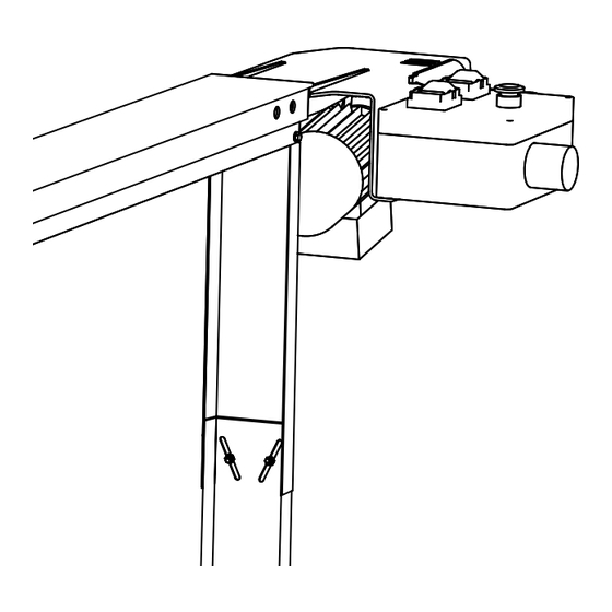
ASSEMBLY: ELECTRIC FEED UNIT Slide the feed unit forks into the guide rail end. Secure the feed unit with bolts in the guide rail. Allen bolt M6x20 Washer 20 mm... - Page 17 OPTIONAL ATTACHMENT ELECTRIC FEED UNIT ASSEMBLY: ELECTRIC FEED UNIT Fit the support leg to the guide rail. Allen bolt M6x20 Flange lock nut M6...
-
Page 18: Assembly: Wire And Wire Attachment
Good job! Now it is time to assemble the wire and the wire attachment. The components needed are in the wire tensioner box. Wire tensioner 01-000339... - Page 19 OPTIONAL ATTACHMENT ELECTRIC FEED UNIT ASSEMBLY: WIRE AND WIRE ATTACHMENT Fasten one of the wire ends to the wire attachment. Pass the wire around the pulley. Open the hatch for better access. Important: Make sure that the wire is led below the guide bolt, which is located after the pulley.
- Page 20 ASSEMBLY: WIRE AND WIRE ATTACHMENT Pass the wire through the wire tensioner and around the pulley. Fasten the wire end to the wire attachment. Tip: Tighten the wire as much as posible by hand before fastening it to the wire attachment.
- Page 21 OPTIONAL ATTACHMENT ELECTRIC FEED UNIT ASSEMBLY: WIRE AND WIRE ATTACHMENT Screw the bolts to the fastening plate on the saw unit. Secure the wire attachment with the nuts. Allen bolt M6x20 Flange lock nut M6 Tighten the wire with the wire tensioner. Important: It is important that the feed unit has the right wire tension to work satisfactorily.
-
Page 22: Adjustment: Support Legs
ADJUSTMENT: SUPPORT LEGS The support legs can be adjusted vertically by loosening the two adjusting bolts. Adjust the height of the support leg until it rests lightly against the ground. Important: The supports legs should just rest lightly against the ground. -
Page 23: Adjustment: Wire Tensioner
OPTIONAL ATTACHMENT ELECTRIC FEED UNIT ADJUSTMENT: WIRE TENSIONER Adjust the wire tension by pulling the ball outwards at the same time as you tighten the tensioning bolt. Note that you have to loosen the counter nut to tighten the wire. Finish the adjustment by tightening the counter nut. -
Page 24: Adjustment: Electric Feed Unit
ADJUSTMENT: NEUTRAL MODE Position the saw unit at the centre of the guide rail. Check that the control lever is in its neutral position. Neutral mode Unscrew the lock bolt from the control lever to reach the pressure bolt. Loosen the pressure bolt. - Page 25 OPTIONAL ATTACHMENT ELECTRIC FEED UNIT ADJUSTMENT: NEUTRAL MODE Press the B4: reverse feed button on the control panel. B4: Reverse feed Tighten the pressure bolt until the saw unit just begins to move backwards. When this happens, you loosen the bolt slightly until the saw unit stops again.
-
Page 26: Control Panel
CONTROL PANEL With the control panel buttons you choose the desired function. During all types of forward processing you need to keep the enabling switch pressed down to enable operation. Red: Stop Saw unit Green: Start Enabling switch Black: – Feed unit White: Start Important: An enabling switch button... -
Page 27: Control Lever
OPTIONAL ATTACHMENT ELECTRIC FEED UNIT CONTROL LEVER With the control lever you control the feeding speed. Operation mode Slip mode Neutral mode Danger: When starting the feed unit, the control lever should always be in its neutral position. Stop Slip mode Operation mode... -
Page 28: Operation: Forward Feed
OPERATION: FORWARD FEED For forward feed, press down the enabling switch button, B5, with your left hand. With your right hand you first start the saw unit by pressing the B2 button, and then start the feed unit by pressing the B4 but- ton. -
Page 29: Operation: Reverse Feed
OPTIONAL ATTACHMENT ELECTRIC FEED UNIT OPERATION: REVERSE FEED For reverse feed, press down the B4 button with your left hand while the control lever is pulld back with your right hand. Control lever Manöverspak Important: During reverse feeding the B4 Danger: Risk of crushing and cutting button has to be pressed down. -
Page 30: Maintenance
’Trouble shooting’ or contact Logosol. Danger: Risk of electric shock and that the Normally, the control lever has to be adjusted a equipment becomes damaged. - Page 31 OPTIONAL ATTACHMENT ELECTRIC FEED UNIT MAINTENANCE Lubrication points Check that the ball bearings always are lubricated. Use adhesive oil in the ball bearing of the clutch. Be careful not to use too much oil. One press on the adhesive oil can nozzle gives enough lubrication (ref.
-
Page 32: Troubleshooting
TROUBLESHOOTING Important: Always stop the machine if you suspect that something is wrong with 1. the wire tension 2. the track in the clutch disc 3. the lock pins in the spindle Important: Check the saw unit and the cutting equipment. If the cutting equipment does not cut as it is supposed to, it can result in poor feeding. -
Page 33: Wiring Diagram
OPTIONAL ATTACHMENT ELECTRIC FEED UNIT WIRING DIAGRAM Circuit diagram Stopp Stopp H.D. Forward/reverse Feed Fram/retur Drift Start Start Saw unit feed SågMatare M 3fas M 3fas 3-phase 3-phase Saw blade Sågklinga T.VG Matarmotor Feed motor Electrical components list Complete terminal box: 6600-001-3027 Enebling switch: 6600-001-0038 Black/white contact: 6600-001-3096 Red/green contact: 6600-001-3095... -
Page 34: Exploded Views
EXPLODED VIEW Lock nut M8 Wire attachment Pulley (6600-001-3023 Flat washer M6 Allen bolt M6x16 Allen bolt M8x35 Tensioner Flange nut M8 Bracket Flange nut M8 Ball Flänslåsmutter, M8 Insexskruv, M8x20 mm Planbricka, M8 Stödben, övre Stödben, nedre... - Page 35 OPTIONAL ATTACHMENT ELECTRIC FEED UNIT EXPLODED VIEW 4 x Allen bolt M6x25 mm 4 x Flat washer M6 Spacer ring 12 mm Worm gear Primary clutch disc Spindle Friction disc (6600-001-3024) Bushing Secondary clutch disc 2 x Angular contact ball bearing (6600-001-3017) Hardened lock pin M6x30 mm (6600-001-3018) Hardened lock pin M6x16 mm (6600-001-3020) Electric motor...
- Page 37 OPTIONAL ATTACHMENT ELECTRIC FEED UNIT...
-
Page 39: Ce Declaration Of Conformity
OPTIONAL ATTACHMENT ELECTRIC FEED UNIT EU declaration of conformity In accordance with Directive 2006/42/EG, Annex 2A Logosol AB Fiskaregatan 2 871 33 Härnösand SWEDEN herewith declares that the Electric Feed Unit has been manufactured in conformity with: The Machinery Directive 2006/42/EG... - Page 40 Fiskaregatan 2, 871 33 Härnösand, SWEDEN +46 611-182 85 | info@logosol.com | www.logosol.com...
Need help?
Do you have a question about the E37 and is the answer not in the manual?
Questions and answers