
Summary of Contents for Ultra Lift 1500
- Page 1 OPERATION MANUAL the best move you’ll ever make! Ultra Lift Corporation, 475 Stockton Avenue, Unit E, San Jose, CA 94126 (800) 346-3057; (408) 287-9400; Fax (408) 297-1199 wwww.ultralift.com; info@ultralift.com...
-
Page 2: Table Of Contents
B. Lift Frame Assembly……………………………………………………………… C. Drive System……………………………………………………………………… D. Electrical System………………………………………………………………….. BATTERY CHARGING…………………………………………………………….. OVERVIEW/MAINTENANCE & INSPECTION PROCEDURES………………… A. Objectives…………………………………………………………………………. B. Regular Maintenance………………………………………………………………. C. Routine Inspection………………………………………………………………… D. Anti-Reverse Brake………………………………………………………………… SPECIFICATIONS: MODEL 1500 POWERED HAND TRUCK……………………. XII. DRIVE SYSTEM ASSEMBLY: EXPLOSION……………………………………….. XII. WARRANTY………………………………………………………………………….. -
Page 3: Introduction
One person equipped with an ULTRA LIFT can safely move most loads weighing up to 650 – 750 pounds. Two people can handle many loads weighing up to 1500 pounds. The factors that determine the maximum load one or two operators can safely handle are the type of move being made (level surfaces, up stairs, etc.);... -
Page 4: Strapping The Load
Lift Frame or is too loose and doesn’t stay in place. To adjust an overly tight fit, lightly tap each bracket toward the center of the Strap Bar. To tighten a loose fit, lightly tap the brackets out. Do this adjustment off the Ultra Lift. Figure 2. Strapping Alternatives... - Page 5 4. With the Strap Bar positioned for your load (see Figure 2) tilt the load forward and slide the Lift Plate under it as you would with any hand truck. 5. Strap the load to the Lift Frame in the following sequence: •...
-
Page 6: The Control Switch
THE CONTROL SWITCH Your ULTRA LIFT has been designed for ease of operation. A single control switch moves the load and the wheels. PUSH the switch to raise the wheels or to lower the load. PULL the switch to lower the wheels or to raise the load. -
Page 7: Breaking Back The Load
The wheels are the fulcrum (break back point) and the load is at maximum distance from the fulcrum. Your ULTRA LIFT takes the work out of breaking back even the heaviest loads. -
Page 8: Moving Over Flat Surfaces
3. At the final destination Ultra Lift takes the work out of setting a heavy load down and also protects the load from damage during the process. The problem with a standard hand truck is that the operator often reaches a point where “the load takes over”... -
Page 9: Loading & Unloading Trucks
BEFORE MOVING A HEAVY LOAD. • LEARN THE LIMITS OF YOUR OWN STRENGTH. Although Ultra Lift provides the power, you mush provide back-pressure in loading trucks, climbing stairs, and overcoming obstacles. • LOAD SHAPE IS AN IMPORTANT FACTOR IN ALL TYPES OF MOVES. -
Page 10: Unloading
Ultra Lift back into the truck and set the load down. 4. Your Ultra Lift has a vertical lifting capability of 36”. Any truck with a bed height of 36” or less can be loaded in one step. -
Page 11: Portable Dock Leveler
PORTABLE DOCK LEVELER Your Ultra Lift can be used as a dock leveler to move loads between docks and trucks that are at different heights. For heavy loads, use the 4 wheel dolly configuration and apply foot pressure to the tripod cross bar for extra counterbalance force as you raise or lower the load. -
Page 12: Stair Moves
STAIR MOVES Moving loads up and clown stairs requires a variation of the procedures used for loading and unloading trucks. An important Ultra Lift safety feature is that the operator is always ABOVE THE LOAD during stair moves. A. CLIMBING STAIRS 1. -
Page 13: Descending Stairs
4. Repeat the second step. Pivot the load forward on the heel of the lift plate and raise the wheels to the third stair as shown. To complete the climb, repeat the third step and continue to repeat steps two and three until the next floor is reached. -
Page 14: Overcoming Curbs & Obstacles
B. THRESHOLDS Thresholds are handled in a similar fashion. The loaded Ultra Lift is backed up to the threshold: 1. PUSH the control switch to raise the wheels at least 18 inches and as much as 36 inches beyond the threshold. -
Page 15: Mechanics Of Operation
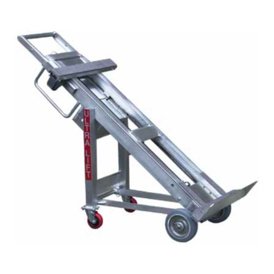
VIII. MECHANICS OF OPERATION Your ULTRA LIFT consists of two primary structural members, a drive system, and an electrical system. Figure 20. Side View: 4 Wheel Dolly Assembled Figure 21. Front View: 2 Wheel Dolly Configuration -13-... -
Page 16: Main Frame Assembly
62” (for working in tight quarters) to 72” for extra leverage and control of tall, heavy loads. The adjustable extension handle makes Ultra Lift a “one size fits all” powered hand truck. 2. Fold Out 4 Wheel Dolly. As shown in Figure 20, the dolly is a tripod attachment that swings out from the Main Frame and locks to the leverage bar to form a 4 Wheel Dolly. -
Page 17: Lift Frame Assembly
To tighten a loose fit, lightly tap the brackets out. Do this adjustment off the Ultra Lift. The strap bar serves as a connection point for many Ultra Lift Accessories, including the Concave Barrel Attachment, Double Cylinder Attachment, File Handling Attachment, Horizontal Move Assembly, Vertical Move Assembly, and Set Offs. -
Page 18: Drive System
C. DRIVE SYSTEM The drive is an electromechanical system that is powered by a non-hazardous 12 volt, deep cycle, spill-proof, sealed battery. As illustrated in Figure 23, the entire drive is mounted to the Main Frame and moves with it. Figure 23 1. -
Page 19: Electrical System
1. Battery. The battery is enclosed in an aluminum housing mounted to the Main Frame. Since the battery is spill-proof, the Ultra Lift can be laid down flat with no concern that chemicals will spill and damage either the machine or floor. The deep cycle battery has been specifically designed to be discharged and recharged for as long as 1 –... - Page 20 The charge plug on the battery charger then connects to the Ultra Lift through the receptacle in the battery housing. This system will not be required at all if you able to charge your Ultra Lift at the end of each workday, as is recommended.
-
Page 21: Battery Charging
IX. BATTERY CHARGING Your Ultra Lift is equipped with a spill proof 12 volt, deep cycle, sealed battery and a fully automatic battery charger. The battery should provide well over a year of reliable service if the charging procedures detailed below are followed consistently. - Page 22 Do Not rotate the plug. Leave the charger plugged in until you are ready to use the Ultra Lift again. DO NOT FORCE THE PLUG! 2. When you are ready to use the Ultra Lift pull the charging plug straight out. DO NOT FORCE THE PLUG! -20-...
-
Page 23: Overview/Maintenance & Inspection Procedures
Models 1500, 1000, 1200 & 1000EV Powered Hand Trucks OBJECTIVES The Maintenance & Inspection Procedures detailed below will keep your Ultra Lift Powered Hand Truck in safe and proper operating condition. The procedures will minimize machine down time due to normal wear on specific components and will help identify any operating problems as they develop. - Page 24 Lubricate each wheel twice per year with lithium grease. 2. Rust Prevention When you are required to use your Ultra Lift in rainy weather at the end of the day, prior to battery charging, run the machine up and down to throw water off the drive screw.
-
Page 25: Routine Inspection
Consistent lubrication, rust prevention and battery charging procedures will eliminate many possible sources of operating problems. It is also very important for each operator to be aware of the general condition of his Ultra Lift. Each machine should be inspected on a daily basis as detailed below: 1. -
Page 26: Anti-Reverse Brake
Lean the machine back and run the Lift Frame up and down twice to confirm that the drive screw operates smoothly. If significant vibration is observed, identify the cause and make necessary repairs before using the Ultra Lift. ANTI-REVERSE BRAKE The anti-reverse brake contains two oilite friction bearings and one roller bearing that are subject to wear and will eventually require replacement. - Page 27 Class U-1, Capacity 33 to 35 Amp Hour DRIVE MOTOR: 1.2 Horsepower D.C. Dual Direction Each Model 1500 is shipped complete with battery, one strap bar, snap-out 4 wheel dolly, adjustable extension handle, and fully automatic battery charger with charging plug attached.
- Page 28 -ii-...
-
Page 29: Warranty
Ultra Lift Corporation or an authorized Ultra Lift Dealer. All warranty service, whether provided by an authorized Ultra Lift Dealer or by Ultra Lift Corporation, must be approved in advance by Ultra Lift Corporation. Contact Ultra Lift Corporation at (800) 346-3057 or (408) 287-9400 to obtain an authorization number.
Need help?
Do you have a question about the 1500 and is the answer not in the manual?
Questions and answers