Table of Contents
Advertisement
Quick Links
a world leader in test & measurement
FINE INSTRUMENTS CORPORATION
341-5, SONGNAE-DONG, SOSA-GU, BUCHON-SHI, KYUNGGI-DO
K O R E A
-TEL: (82-32) 668-6042 -FAX: (82-32) 656-5844
-E-mail: fine@finest.co.kr
© Copyright 2003 Fine Instruments Corp. All right reserved.
Specifications subject to change without notice.
Litho in Korea.
Model 716
Automotive Multimeter
FINE INSTRUMENTS CORPORATION
USER'S
MANUAL
Advertisement
Table of Contents

Summary of Contents for FINE INSTRUMENTS CORPORATION FINEST 716
- Page 1 Model 716 Automotive Multimeter USER’S MANUAL a world leader in test & measurement FINE INSTRUMENTS CORPORATION 341-5, SONGNAE-DONG, SOSA-GU, BUCHON-SHI, KYUNGGI-DO K O R E A -TEL: (82-32) 668-6042 -FAX: (82-32) 656-5844 -E-mail: fine@finest.co.kr © Copyright 2003 Fine Instruments Corp. All right reserved.
- Page 2 Basic Specifications DC Voltage : 0 to 1000 V AC Voltage : 0 to 1000 V (40 Hz to 2 kHz) Basic Accuracy : DC voltage – 0.1 % AC vol t age – 0.5 % RPM (4-stroke) : 120 to 20000 RPM RPM (DIS &...
-
Page 3: Table Of Contents
CONTENTS 1. SAFETY INFORMATION This manual contains information and warnings that must be followed for operating 1. Safety Information the meter safely and maintaining the meter in a safe operating condition. 2. Introduction If the meter is not us ed in a manner specified in this manual, the protection 3. - Page 4 WARNING CAUTION To avoid electrical shock hazard or damage to the meter, do not exceed the input Disconnect the test leads from the test points before changing functions to avoid limits shown in the table below : damaging the meter when testing above 350 V AC. TERMINALS MAXIMUM INPUT FUNCTION...
-
Page 5: Introduction
FEATURES 2. INTRODUCTION digit, 50000 count (primary) and 9999 count (secondary) dual display with This meter is a handheld and battery operated professional automotive multimeter bar-graph. (Frequency range : 99999 counts) des igned to provide troubles hooting solutions to the most difficul t problems encountered with today’s sophisticated automotive electronic systems. -
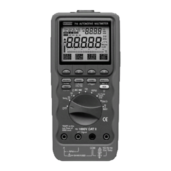
Page 6: Controls And Indicators
1. LCD display digit, 50000 count (primary) and 9999 count (secondary) 3. CONTROLS AND INDICATORS dual display with bar-graph On screen menu selection pushbuttons Press this pushbutton momentarily to select trigger lev els. Pres s this pushbutton for more than 1 sec ond to toggle between positive and negative trigger slopes. - Page 7 Press this pushbutton momentarily to select ranges in the This annunciator indicates the Memory function is activated. manual ranging mode of most functions or number of cylinders on Dwell function. Press this pushbutton momentarily to toggle annunciator indicates the HOLD functions is selected between the PFI mode and the TBI mode when measuring on- annunciators indicate the Auto Hold function time of fuel injectors.
-
Page 8: Basic Meter Functions
4-1. Voltage (V) 4. BASIC METER FUNCTIONS 1. Set rotary selector to position. Making Measurements and Tests The meter defaults at DC. All measurements and tests are made by first setting the rotary selector switch to a 2. Press menukey 2 momentarily to function setting (so that the meter is put in the default measurement function) and select AC, and press t w i c e... -
Page 9: Dual Display Rpm
4-2. Dual Display RPM 4-3. Temperature T his function i s avai lable for the 1. Set rotary selector to T e m p . primary functions ; DC mV, AC mV, DC position. V, AC V, Dwell, ms-Pulse, and Duty Cycle. -
Page 10: Resistance ( )
4-4. Resistance ( ) 4-5. Continuity ( CAUTION CAUTION Tu rn off p ower and dischar ge all Tur n th e pow er OF F on the t est capacitors on cir cuit to be tested cir cuit. A beeper ton e do es not b efor e attem pting incircu it... -
Page 11: Diode Test ( )
4-6. Diode ( ) Test 4-7. Frequency CAUTION 1. Set rotary selector to Hz position. T ur n th e pow er OFF on the test 2. Insert black lead into COM terminal circuit. and read lead into Hz terminal. 1. -
Page 12: Rpm
4-8. RPM (primary display) 4-9. Fuel Injection On Time WARNING This function applies to both Port Fuel Injectors (PFI) which operate with a Be sur e the inductive pickup is in single On Time pulse and Throttle Body t he ter m in als m ar ked “ - RPM +” Injectors (TBI) which operate with twin w hen m easur in g RPM’s. -
Page 13: 4-11.Duty Cycle
4-10. Dwell 4-11. Duty Cycle 1. Set rotary selec tor to ms-Pulse, 1. Set rotary selector to ms-Pulse, Dwell, Duty position. Dwell, Duty position. 2. Press menukey 2 to select Duty 2. Press menukey 3 to select Dwell function. function. The meter defaults at 4 cylinders ( 3. -
Page 14: 4-12.Charging System Test
4-12. Charging System Test • “ ” not displayed : Check wiring and battery leads. • “ ” displayed : Good battery, proceed. Charging system problems often are • “ ” and “ ” displayed : Low Battery, correct before proceeding. identified with a No-Start complaint. -
Page 15: Ground Test
4-13. Ground Test SECONDARY DISPLAY PRIMARY DISPLAY (Amount of Voltage Drop) (Good) < 0.1999 V This function is designed to locate bad (Suspect) 0.2000 ~ 0.3999 V grounds , voltage drops, intermi ttent (Bad) 0.4000 ~ 1.9999 V c onnec tions, or any sourc e of high (Open) 2.0000 V res istanc e in automoti ve electrical... - Page 16 4-14. O Sensor Also during this test the menukey 3 (Lean) or menukey 4 (Rich) might be pressed to send out a rich command or a lean command for 5 seconds, which will make the “Lean” or “Rich” annunciator on menu screen flash depending upon which was This is a very efficient method to check commended.
-
Page 17: 4-15.Ac Or Dc Current ( )
4-15. AC or DC Current ( 4- 16. Battery Drain Test WARNING This functi on measur es the c ar’s battery current when it is turned off. D o not measur e an y cir cuit that This test will run continuously so the draws more than the current rating Auto-Power-O ff feature wi ll be of the installed fuse. -
Page 18: Advanced Features
5-3. Manual and Auto Ranging 5. ADVANCED FEATURES Press the button momentarily to select manual ranging, and the meter will 5-1. MIN/MAX Mode remain in the range it was with LCD annunciator turned off. Press this button momentarily again to step through the ranges. Press this button for more than 1 Press the button momentarily to activate MIN/MAX(Record) mode with LCD second to resume autoranging. -
Page 19: Rpm Selection
The 4 selectable trigger levels are cycled through as follows : 5-7. Hold or Auto Hold • RPM : +TRIG +TRIG +TRIG +TRIG Press the button momentarily to activate the Hold function with LCD • Dwell, ms-Pulse, Duty annunciator turned on. Press this button momentarily again to exit Hold –TRIG –TRIG –TRIG... -
Page 20: Backlight
5-10. Auto-Power-Off Recall : Selec t Recall to review the stored data by pressing the menukey 2. The meter automatically turns off after approximately 30 minutes of no activities to When you press the menukey 2, the last extend battery life. memory location number used in the prev ious memory operation wil l You can enable or disable the Auto-Power-Off mode. -
Page 21: Maintenance And Replaceable Parts
6. MAINTENANCE AND REPLACEABLE PARTS WARNING To avoid false readings, which could lead to possible electric WARNING shock or personal injury, replace the battery as soon as the low battery indicator appears. To avoid electrical shock or personal injury, remove test leads and any input signals before replacing the battery or fuse. -
Page 22: Specifications
Pollution Degree 7. SPECIFICATIONS E.M.C. : Meets EN 61326 : 1997 + A Safety & Compliances Size (H x W x D) : 8.19 x 4.05 x 2.13” (208 x 103 x 54 mm) Maximum voltage between any terminal without mounted accessory and earth ground : 600 V dc/ac (but, 1000 V dc/ac peak for functions) - Page 23 ms-Pulse/Duty Cycle : Meas ure the ti me signal is ON or O F F i n DC Current milliseconds or in % Range Resolution Accuracy 5.0000 A 100 µA 0.5 % + 10 d Close-Case calibration : No internal adjustments needed 0.5 % + 20 d 10.000 A 1 mA...
- Page 24 Temperature Dwell Resolution Accuracy * Range * Resolution Accuracy Range 1.2 / krpm + 2 d -50 C to 0 C 0.1 C 0.0 - 356.4 ±3.0 C 0 C to 100 C 0.1 C ±1.0 C 4 Selectable trigger levels and ± trigger slopes 100 C to 1300 C 0.1 C ±3.0 C...
Need help?
Do you have a question about the FINEST 716 and is the answer not in the manual?
Questions and answers