Table of Contents
Advertisement
Quick Links
Advertisement
Table of Contents

Subscribe to Our Youtube Channel
Related Manuals for MCDonald Electraflow

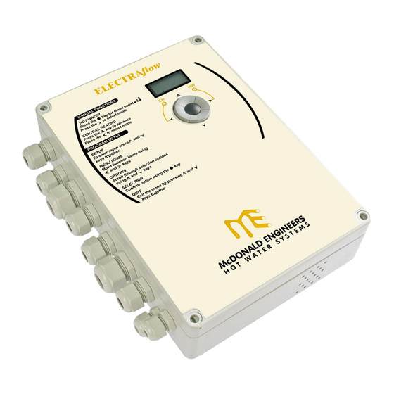
Summary of Contents for MCDonald Electraflow
- Page 1 Electraflow - Multi-Channel Timer 1 of 31 3MUI042 Rev16.09.16...
-
Page 2: Table Of Contents
Controller (3MF042_1) Remote Boost Button (3MF042_2) Product Summary ......................3 Specification ........................4 Installation ........................5 3.1. Mounting ........................5 3.2. Connections ........................ 6 3.2.1. Heater and Control Supply Connections ..............6 3.2.2. Central Heating Pump Connection ................ 10 3.2.3. Central Heating Room Thermostat Connection ............. -
Page 3: Product Summary
1. Product Summary The Electraflow Controller provides connections for up to five 3KW immersion heaters. These outputs are implemented as two isolated groups to allow for single or dual supply systems. In addition the Controller provides control of the central heating pump. -
Page 4: Specification
2. Specification Purpose of control Sensing control Classification Type 1.B Action, micro-disconnection on operation Contact rating 230VAC Suitable for heating element up to 3KW Control power supply 230V AC 50Hz 4W Load power supply 230V AC 50Hz 5 x 3KW + 700W (heating pump) Boost duration 30, 60 and 120 min Operating... -
Page 5: Installation
3. Installation 3.1. Mounting Fig. 2 Enclosure dimensions and mounting points 180mm 165mm Ø5mm x 4off Fix the unit securely in place using the 4 off 5mm dia. mounting holes in the enclosure. The mounting holes are located directly behind the enclosure lid screws. The drawing above shows the location and fixing centres of the holes. -
Page 6: Connections
3.2. Connections 3.2.1. Heater and Control Supply Connections The connection of the heater supplies to the power distribution equipment is dependent on the required system configuration. As such it is the responsibility of the system designer and the installation engineer to ensure that the installation wiring and associated switchgear is arranged logically for the intended application. - Page 7 Fig. 3 General wiring diagram of the Controller: Note. If the Controller has been configured to not provide all the possible connectivity, then the respective cable glands will have been replaced with blanking plugs. If for any reason any of the fitted glands are not used for a particular installation then these must be also be blocked off using suitable blanking plugs to prevent any access to the inside of the enclosure.
- Page 8 Location of heater connections inside the Controller: Note. Each of the immersion heater outputs is internally fused, using a standard 1”x¼” 15A fuse in a PCB mounted fuse holder. Warning – All immersion heaters must have their in-built high limit thermostat connected directly in-series with the element to provide safety protection.
- Page 9 Connections on Base Board: Fig1. Connection Description Location Connector Heater1A Lout Lout Live OUT terminal for Heater1A Heater1A W Common earth connection for earth continuity of Heater1A Heater1A N Nout Neutral OUT terminal for Heater1A Heater1B Lout Lout Live OUT terminal for Heater1B Heater1B W Common earth connection for earth continuity of Heater1B...
-
Page 10: Central Heating Pump Connection
3.2.2. Central Heating Pump Connection The Controller provides connection for a CH pump (up to 700W). The heating pump is connected directly to the Controller, the supply being derived internally from the Controller’s power supply. The CH pump connection is independent of the room thermostat interface so that the Controller can provide a pump overrun period (fixed time period of 5 mins). - Page 11 Fig1. Connection Description Location Connector Remote boost switch Gnd return Remote boost switch input. Note this is only intended for use with dedicated Boost switch. Location of control connections inside unit: 11 of 31 3MUI042 Rev16.09.16...
-
Page 12: Heater Configurations
When a boost is required the CH1 Immersion will come on to ensure full kW input to the unit. The Electraflow Controller provides connections for up to five 3KW immersion heaters. The functionality of each immersion heater is determined by the Presets item in the Engineers Menu. - Page 13 Fig. 4 Controller Wiring Schematic 13 of 31 3MUI042 Rev16.09.16...
-
Page 14: Operating Instructions
4. Operating Instructions 4.1. General Use The Controller provides a 2 line by 8 character backlit display and two LED’s to show the system status. The display is used to show the operating status of the unit whilst in Status display mode and is also used to show configuration information whilst in either the Users Menu or Engineers Menu. -
Page 15: General Functionality
4.2. General Functionality The unit normally operates in Status display mode. In this mode the first line of the display shows the current time, whilst the second line displays various changing status messages. The following table lists the standard status messages that the controller may display: Status Display Description... -
Page 16: Hw & Ch Mode Selection
In addition to the display, two indicators labelled ‘CH’ and ‘HW’ provide status information. The ‘CH’ indicator is on when the CH 7day timer is on or the CH has been manually advanced. The ‘HW’ indicator is on when the HW 24hr timer is on or the HW has been manually boosted. -
Page 17: Remote Boost Button
Fig. 5 Boost Button Operation 30 min 120 min 60 min After each boost key-press the display will briefly show the duration period set. The display will then revert back to showing the normal alternating status messages. The boost function can be cleared at a later time by a single press of the boost button. -
Page 18: Ch Advance Control
4.2.4. CH Advance Control The Controller’s must be set to to use the CH advance M o d e O F F t i m e d function. The CH 7day timer settings may be manually advanced using the CH advance button (Up key). -
Page 19: Configuration
4.3. Configuration The various Controller settings which determine its operation are configured using the two menus; Users Menu and Engineers Menu. Once in either of these menus, the four cursor keys together with the Boost key are used to review and revise the settings. The left and right cursor keys are used to traverse across the menu items and sub-menu items (where applicable). -
Page 20: Selecting On And Off Times
To confirm the entered timer settings, press the Boost key. Once confirmed the menu or sub- menu will be re-displayed. At any time whilst in a timer setting, pressing the up and down cursor keys simultaneously will exit from the menu, and place the controller back in Status display mode. Any changes made to the time setting will be saved. -
Page 21: Date
4.3.2.1. Date The item is used to set the calendar (day-of-month, month and year). The S e t D a t e Controller automatically switches between GMT and BST at the appropriate date and time, and also automatically compensates for leap-years up to the year 2099. The year or day-of-month will flash to show which item is currently being changed. -
Page 22: Exit
On entry the display shows the current day on the first line. The ‘day’ will be flashing to show it is the current item. Use the Left and Right keys to select a specific day. To view and edit that day’s time periods, press the Boost key. Refer to section 4.3.1 for editing specific time periods. - Page 23 Fig. 7 Users Menu Structure: 23 of 31 3MUI042 Rev16.09.16...
-
Page 24: Engineers Menu
4.3.3. Engineers Menu The Engineers Menu is used to configure various Controller settings that are generally only changed during installation of the system. The items contained in this menu are as follows: Item Description P r e s e t s Used to allocate heaters to the CH and HW sections T a r i f f Used to preset the settings of the HW 24hr timer... -
Page 25: Tariff
4.3.3.2 Tariff NB – On a THERMflow Thermal Storage Type Unit – the off peak tariff should be used during the early hours of the morning, to bring the unit up to operating temperature. The item determines which set of pre-configured time settings are used for the T a r i f f HW 24hr timer. -
Page 26: Ch Timer
4.3.3.4 CH Timer The item is used to configure the Controller’s CH 7day timer. This item is T i m e r identical to in the User Menu (refer to section 4.3.2.3) and is incorporated into T i m e r the Engineering Menu for convenience when commissioning the system. - Page 27 Fig. 8 Engineers Menu Structure: 27 of 31 3MUI042 Rev16.09.16...
-
Page 28: Internal Operating Temperature
5. Internal Operating Temperature If a high ambient temperature fault condition occurs, the Master will turn off all the heaters until the fault condition has been resolved. The ‘high ambient temperature fault’ status message is displayed and both LED’s will flash alternately during the fault condition. The RBB will also flash to help draw attention to the fault. - Page 29 Notes: 29 of 31 3MUI042 Rev16.09.16...
- Page 30 Notes: 30 of 31 3MUI042 Rev16.09.16...
- Page 31 Copyright © 2006 3Minds Limited. All rights reserved. QUEENSWAY INDUSTRIAL ESTATE, GLENROTHES, FIFE KY7 5QF. Tel: 01592 611123 Fax: 01592 611166 Email: sales@mcdonaldwaterstorage.com Internet: www.mcdonaldwaterstorage.com 31 of 31 3MUI042 Rev16.09.16...
Need help?
Do you have a question about the Electraflow and is the answer not in the manual?
Questions and answers