Advertisement
Available languages
Available languages
U 468 931 012 911-08
Installation and
Operation Instructions
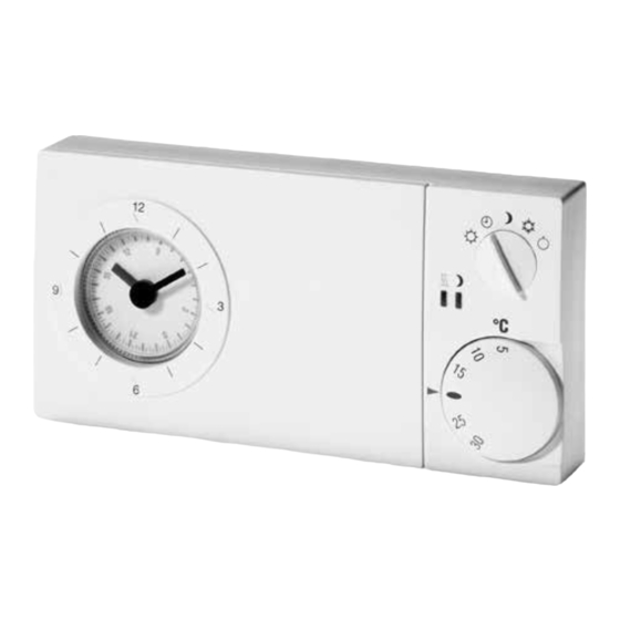
Electronic
Clock Thermostat
easy 3s
Warning!
The device may only be opened and installed accor-
ding to the circuit diagram on the device or these
instructions by a qualified electrician. The existing
safety regulations must be observed.
Appropriate installation measures must be taken to
achieve the requirements of protection class II.
This independently mountable electronic device is
de-signed for controlling the temperature in dry and
e nclosed rooms only under normal conditions. The
device confirms to EN 60730, it works according
o perating principle 1C.
1. Applications
The easy 3s electronic clock thermostat is designed for room
temperature control in conjunction with:
• h eating systems, e.g. hot-water heaters, convector heaters
or floor heating
• e lectric convector heaters, ceiling and storage heating
• night-storage heaters
• c hillers
• c irculation pumps
• b urners and boilers
• h eat pumps, etc.
• a irconditioning applications (cooling only)
Features
•
v ery simple operation
• c omfort and setback temperature adjustable
5 operating modes (by rotary switch) for:
•
➩ permanent comfort temperature (5...30°C)
➩ permanent setback temperature (5...30°C)
➩ clock mode (automatic)
➩ frost protection (5°C fixed)
➩ OFF
•
Indicator lamps for: ➩ heat demand
➩ setback mode
a vailable with daily or weekly timer
•
•
c ontrol by phone remote switch possible
•
o utput signal PWM or ON/OFF regulation (adjustable via
jumper)
•
r elay output, 1 x changeover contact
•
remote sensor optional
•
emergency operation at sensor failure
•
h inged cover
•
n ew design 2000
2. Function description
The clock thermostat is designed to control the room tem-
perature.
In the automatic mode, a changeover is effected between
comfort and setback mode by the built in timer.
Optionally remote sensor can be used instead of built-in
sensor.
In setback mode the green indicator lamp lights up.
If room temperature drops below set value, heating will start,
the red indicator lamp will light up.
Indicator lamps
Red
indicates when controller demands heat,
Green
indicates when setback mode is activated.
Red
fl ashing for failure. Operating voltage to be swit-
ched OFF and ON again.
Controller heat demand at PWM
If room temperature drops below the set value, heating mode
will start. The controller output is in the form of pulses of
varying length (PWM). The length of the pulses depends on
the difference between set and actual room temperature.
The sum of pulse and pause times can be selected with J4
(between 10 or 25 min.).
If there are large temperature differences, the controller will
switch ON or OFF permanent, e.g. when changing over to
temperature setback mode. PWM should only be used for
current ≤ 10A
On
Off
Temperature
set temperature
10/25 min
Fig. 1: C haracteristic of impulse pause ratio de p en d ing on
temperature
Cycle time setting
For inert applications (e.g. burners) we recommend the long
cycle time.
For quick applications (e.g. electric direct heaters) we re c om-
mend the short cycle time.
Plug-in jumper J4
Time
(right side of board)
Double-pole jumper
25 min
connection
(as-delivered condition)
Single-pole jumper
10 min
connection
Heat demand of the controller at ON/OFF regulation
When room temperature drops below set temperature the
output will be switched on, whereas it will be switched off,
when set value is exceeded.
ON
OFF
Hysteresis
set temperature
Fig. 2: ON/OFF regulation
Plug-in jumper J3
Regulation
(right side of board)
Double-pole jumper
ON/OFF
connection
Single-pole jumper
PWM (as delivered condition)
connection
Phone remote switch
(only available at special variants)
Via an external phone switching device the conroller can be
put into mode of comfort or setback temperature. As long
as contact (terminal 19) is closed, the comfort temperature
will be "used". This function ist activated in the modes 2
automatic, Ñ setback temperature permanent and P
Frostprotection.
3. Installation
The controller should be arranged in a place within the room
which:
• i s easily accessible for operation
• i s free from curtains, cupboards, shelves, etc.
• e nables free air circulation
• i s free from direct sun radiation
• i s free from draughts (e.g. opening of windows and doors)
• i s not affected directly by the source of heat
• i s not located on an external wall
• i s located approx. 1,5 m above floor level
Mounting directly on conduit box or with adapter frame ARA
easy.
Electric connection
Warning! Disconnect electric circuit from supply.
Proceed as follows:
• p ull off temperature setting knob
• p ush retaining hook outwards using screwdriver
• r emove housing cover
• m ake connection in compliance with wiring diagram
(see housing cover).
• w atch notes
Remote sensor
Having connected the remote sensor, the integral sensing
component will be switched off automatically.
The sensor cable is extendable up to a length of max. 50m.
Please use a two-core 230V cable with a cross section of 1.5
mm2.
The sensor cable (F 193720) should be installed into a protecti-
on tube (pocket). This facilitates later replacement.
In case of failure (break or short-circuit) the controller switches
into emergency operation:
at PWM: 30% heating capacitiy
at ON/OFF: Relay OFF
Warning! Sensor cables carry operating voltage.
4. Technical data
Temperature setting range:
5...30°C
comfort temperature
5...30°C
setback temperature
approx. 5°C fixed
frost protection
Regulation
proportional controller
(due to PWM quasi-continuous, see Fig.1)
Cycle period
adjustable 10 or 25 min.
(sum of PWM ON and OFF times)
Proportional band
1,5K
Hysteresis
~0,5K, ≤ 10A see Fig. 2
~0,5K at 16A and use with remote sensor
~2,5K, at 16A without remote sensor
ON/OFF regulation
adjustable via jumper
Output
relay, 1 volt-free* changeover contact
Switching current
10mA...16 A cos ϕ = 1
Heating
max. 4 A cos ϕ = 0,6
Cooling
10mA ...10A cos ϕ = 1
max. 1,5 A cos ϕ = 0,6
Switching voltage
24...250V AC
Mode selector switch
comfort / automatic / setback /
frost protection / OFF
Phone remote switch
Input for 230V AC (via an external
(as variant)
phone switching device)
Indicator lamp:
red
controller demands heat
green
setback mode
Temperature sensor:
internal
Remote sensor
type F190021 (wall mounting)
Sensor characteristics
type F193720 length 4m
both extendable up to 50m
42kΩ at 20°C
26kΩ at 30°C
Range limitation
inside setting knob
Clock:
<10 min./year
accuracy
every 15 min. with daily timer
switching time setting
every hour with weekly timer
temperature
power reserve
approx. 100 h
Protection class of housing
IP 30
Degree of protection
II (see Warning 1)
Ambient temperature
0...40°C, without condensation
Storage temperature
–25...65°C
Pollution degree
2
Rated impulse voltage
4 kV
Ball pressure test
75 ± 2 °C
temperature
Voltage and Current for the
230 V, 0,1 A
for purposes of interfernce
measurements
Dimensions
160 x 80 x 36 mm
Weight
approx. 220 g
Energy class
IV = 2 %
(acc. EU 811/2013, 812/2013, 813/2013, 814/2013)
* The volt-free contact of this mains-operated unit does
not ensure the requirement for the use of safety ext-
ra-low voltage (SELV).
For units with 230 V supply voltage
Type
easy 3st with daily timer
easy 3sw with weekly timer
Article-Nr.
easy 3st
517 2701 51 100
easy 3sw
517 2702 51 100
Operating voltage
195...253 V AC 50/60 Hz
Power consumption
< 1,5 W
For units with low voltage output
Type
easy 3st 1mA with daily timer
easy 3sw 1mA with weekly timer
Article No.
easy 3st 1mA
517 2711 51 100
easy 3sw 1mA
517 2712 51 100
Operating voltage
195...253V AC 50/60Hz
Switching current
>1 mA, >1V or max. 10(4) A AC
Power consumption
< 1,5 W
5. Wiring diagram
Symbol explanation
U Heaing
P Cooling
Remote sensor
%
Phone remote switch
Note
For heating applications
• connect n/c actuators to terminal 2.
• connect n/o actuators to terminal 3.
For cooling applications
• connect n/c actuators to terminal 3
• connect n/o actuators to terminal 2
• T o use the red lamp as indicator for "cooling ON", connect n/o
actuators to terminal 2
• W hen mode selector switch is in OFF position
actuators will be closed logically.
6. Operation
Temperature setting
1
Comfort temperature (daytime temperature)
i s set by means of externally visible seting knob (1)
2
Setback temperature (night temperature)
i s set by means of adjustment knob (2) beneath cover.
Time setting
3
b y putting one finger on dial (3) and turning in any direc-
tion, you can set the time.
4
A rrow (4) points to the selected time.
Switching time setting
5
B ring movable tappets (5) into required position using a
pointed object.
Outer ring = comfort temperature
Inner ring = setback temperature
Mode selector switch (6) – externally
6
É C omfort temperature, permanent
2 A utomatic mode, time-controlled changeover
between comfort and setback temperature
Ñ S etback temperature, permanent
P F rost protection, permanent (5°C)
O FF, there is no control activity. The controller itself is not
disconnected from operating voltage.
3
4
5
6
2
1
This product should not be disposed of with
household waste.
Please recycle the products where facilities for
electronic waste exist. Check with your local
authorities for recycling advice.
n/c and n/o
Advertisement
Table of Contents

Summary of Contents for Easy 3s
- Page 1 Note at ON/OFF: Relay OFF 1. Applications For heating applications Warning! Sensor cables carry operating voltage. • connect n/c actuators to terminal 2. The easy 3s electronic clock thermostat is designed for room • connect n/o actuators to terminal 3. temperature control in conjunction with: 4. Technical data Temperature set temperature For cooling applications • h eating systems, e.g. hot-water heaters, convector heaters...
- Page 2 4. Données techniques 1. Applications Plage de réglage de température : température confort 5…30°C hors-gel température réduite 5…30°C Le thermostat à horloge électronique easy 3s peut être utilisé éteint 5°C env. (ferme) pour régler la température des pièces en association avec: Régulation régleur proportionnel (quasi continu température valeur de consigne l es systèmes de chauffage, tels que chauffage à eau chaude,...
- Page 3 Umschaltbar ca. 10/25 min Sollwert Temperatur U Heizen P Kühlen Fernfühler (Summe von Ein- und Telefonfernschalter Auszeit der PWM) Der elektronische Uhrenthermostat easy 3s kann verwendet Proportionalband 1,5K werden zur Raumtemperaturregelung in Verbindung mit: 6. Bedienung 10/25 min Hysterese ~0,5K, ≤10A s. Bild 2 • H eizanlagen wie: Warmwasser-, Konvektor- oder...
Need help?
Do you have a question about the 3s and is the answer not in the manual?
Questions and answers