
Related Manuals for Formulatrix NT8

Summary of Contents for Formulatrix NT8
- Page 1 ’ UIDE LCP & PPLIES TO LATE PTIONS RIGINAL NSTRUCTIONS...
- Page 3 User’s Guide Original Instructions Second Edition Revised June 2018 NTG-V25R314 © 2018 Formulatrix. All Rights Reserved.
- Page 5 Support, Europe Phone: +31 652 451106 flip@formulatrix.com Acknowledgements The NT8 was developed in collaboration with Vadim Cherezov of The Scripps Research Institute (TSRI) and the JCIMPT Center led by Ray Stevens and supported by the NIH Common Fund in Structural Biology.
-
Page 7: Table Of Contents
Task List Properties..........................25 Device View............................25 Plate Library............................26 Status Bar............................26 Rock Maker Integration Tab......................27 Chapter 9: Setting Up the NT8 Hardware..............31 Installing a Low Volume Protein Block..................31 Installing a High Volume Protein Block..................32 Installing a Low Volume Tip Caddy...................32 Installing the Reference Plate......................33 Installing a High Volume Tip Caddy..................33... - Page 8 Chapter 14: LCP Experiment Dispenses..............53 Chapter 15: Running Rock Maker Experiments with NT8........57 Chapter 16: System Maintenance................59 Chapter 17: Troubleshooting and FAQs..............63 Appendix A: Toolbar Buttons..................65 Index..........................66...
-
Page 9: Chapter 1: Introduction
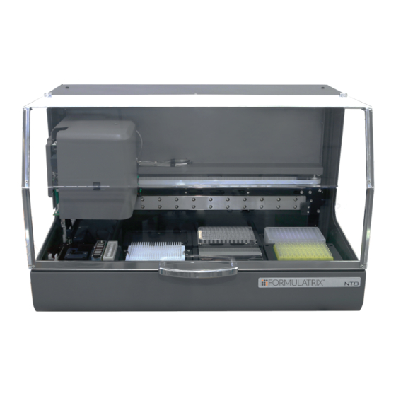
Thank you for purchasing the NT8, an automated nanoliter volume liquid handler with drop dispensing capabilities. Your NT8 must be used in the manner described in this user’s guide. Any other use may result in damage to your NT8 or personal injury. Formulatrix, Inc. - Page 10 Symbols and Conventions Convention Description This icon denotes a caution and advises you of precautions to take. This icon denotes a prohibited action. This icon denotes a compulsory action and advises you of actions you must take. This icon denotes a caution relating to electric shock and advises you of precautions to take.
-
Page 11: Chapter 2: Safety Information
The safety recommendations in this guide are basic guidelines. If the lab where the NT8 is to be kept has additional safety guidelines they should be followed as well, along with all applicable national and international safety codes. -
Page 12: Mechanical Hazards
Mechanical Hazards The NT8 is a complex electromechanical device. Only persons with the proper training should service or operate the product. All facilities to the product must be disconnected before servicing, or injury may result from the automatic operation of the equipment. -
Page 13: Chapter 3: Requirements And Specifications
The NT8 should be placed on a sturdy table that has dimensions of at least 120 cm (47.2”) wide by 80 cm (32.5”) long. The water carboy should be placed to either the left or right of the NT8. The waste carboy should be placed under the table. -
Page 14: Electrical Requirements
Electrical Requirements ● Robotics: 100-240 V, 50-60 Hz, 130 W typical, 200 W max ● Standard or European electrical outlet Confirm that the power supply requirements are properly met to avoid material damage and fire. The power supply for the system must meet or exceed electrical requirements of the system to avoid damage and risk of fire. -
Page 15: Chapter 4: Overview
Optical encoders monitor the positioning of each motion axis and tell the NT8 to alert you as soon as a motion error is detected while Tip Touch Sensing surveils tip-to-plate contact and... -
Page 16: Options
LCP models include a lipid mixer and an automatic LCP calibration system. The lipid mixer attaches to the NT8’s deck, and is controlled by the software to ensure the right number of mixing cycles are applied to the syringe. The automatic calibration system ensures the syringe tip is centered to within 50 μm. -
Page 17: Chapter 5: Hardware Overview
Using the NT8 requires a working knowledge of its components. The two major assemblies of the NT8 are the head and the deck. Both are located on the front of the NT8. The head primarily contains tools to aspirate and dispense liquids, and the deck contains the plates, tip caddies, protein source(s), and the wash and waste stations. -
Page 18: The Nt8 Head
● HV tips are located at the bottom-right of the NT8’s head. ● If you have the LCP option, an LCP lever is located on the front of the NT8’s head. The LCP syringe mount, compatible with Hamilton LCP syringes, is found on the left side. -
Page 19: Accessories
LCP syringe coupler, six short 26 gauge needles, five LCP sandwich plates and seals, and two 100 µL syringes. Note: Your NT8 must be equipped with the LCP option in order for it to work with the LCP starter kit. - Page 20 Figure 5-12. Ball point hex keys. ● Power Cable – The power cable is approximately 15 feet long, and is used to conduct power to your NT8. Figure 5-13. Power cable.
- Page 21 ● Wash and Waste Tubes – The wash and waste tubes connect to the wash and waste carboys and the wash and waste inputs at the back of the NT8. ● LV Head and LCP Head Calibration Pin – The pin is used for calibrating the LV head and the LCP head.
-
Page 23: Chapter 6: Initial Setup
INITIAL SETUP Setting Up the NT8 Setting up the NT8 for initial use means connecting all of the cables, setting up the water and waste carboys and installing the .NET framework as well as the FTDI drivers to your computer. A diagram of the setup is shown below for reference. - Page 24 Repeat steps a-f for USB Serial Converter B. Your NT8 is now ready for use. If you want to, you can find the NT8’s icon in the NT8’s files and make a shortcut for your desktop by right-clicking and...
-
Page 25: Adding Plate Types
NT8 and farthest away from you). ● You have installed a Low Volume (LV) tip into LV attachment 1 (tip position 1 is the one closest to the inside of the NT8, and farthest away from you). - Page 26 2. Fill in the Name and Description boxes. 3. Using the plate data sheet that came with your plate, enter the plate Size dimensions, and select the drop type from the Drop Type drop- down menu. 4. Optional: If you don’t have the plate data sheet or know the plate height, click the ellipses button next to the H text box to open the plate height wizard.
- Page 27 ALIBRATING THE ELL AND FFSET When you calibrate the well and/or drop offset, you are helping the NT8 determine the distance from the center of one well or drop to the center of the next well or drop. 1. In the Well or Drop properties table, select Offset and click .
- Page 28 ROPERTIES You can define the pre-dispense properties for the LCP attachment if your NT8 is capable of dispensing LCP drops. 1. Click the Add LCP Pre-Dispense button 2. Click the LCP Pre-Dispense node on the plate properties tree to select it.
-
Page 29: Chapter 7: Configuring The Humidifiers
Level to Speed Up is the low humidity level limit; when the sensors detect that the humidity levels have reached this point they will speed up. These settings affect the humidifier 1 in your NT8. Lower Level to Switch ON is the humidity Humidifier 1 point at which humidifier 1 will activate. -
Page 31: Chapter 8: Software Overview
The Toolbar is a horizontal strip of buttons at the top of the screen that allows you to open, save, and edit Task Lists, which is a list of directions the NT8 follows to complete a dispense; interact with the NT8 hardware, open the Options menu, and more. -
Page 32: Task List
The Task List panel is divided into two tabs: the Task List and Task List Properties. The Task List is where the list of commands are displayed that the NT8 will perform. These actions are added by you using the software. -
Page 33: Task List Properties
NT8 hardware. Figure 8-3. Device View. 1 – Waste Hopper. The waste hopper is where the NT8 disposes low volume (LV) tips after use. 2 – Protein Station. The protein station is where you tell the software how much volume is in your protein tray, and which columns to aspirate from. -
Page 34: Plate Library
5A, 5B, 5C – Microplate Stations. These areas represent places where you can put plates on the NT8. If you have a High Volume Protein Tray, you can put it on the upper-left microplate station (5C on this diagram, also known as microplate station 3). -
Page 35: Rock Maker Integration Tab
ANEL The Head Panel displays the three types of heads available with the NT8: LCP, Low Volume (LV) and High Volume (HV). The active head type is indicated by a green background. Figure 8-6. Head panel. Rock Maker Integration Tab If you have Rock Maker, there is a second tab next to the Experiment Designer tab. - Page 36 You can select either Always, Protein, or Plate for Change Tips. If you select Always, the NT8 will change the LV tips after they are used to dispense to one row on your plate. If you select Protein, the NT8 will change tips when it must start dispensing a new type of protein sample.
- Page 37 C – Plate View. The plate view table represents the plate currently being dispensed, with the stock or protein volume and target well or drop information for the current stock. D – Dispense Properties Panel. The Dispense Properties panel displays information about the liquid class, source, destination, and dispense volume.
-
Page 39: Chapter 9: Setting Up The Nt8 Hardware
Before running a dispense, you need to prepare the hardware. If you're not familiar with the components, please see “Chapter 5: Hardware Overview”. This topic will explain how to station every possible component of the NT8. You may not have to set up each component for a dispense, so make sure to refer for the chapter about your particular setup before prepping your hardware to avoid unnecessary hardware setup. -
Page 40: Installing A High Volume Protein Block
The Low Volume (LV) tip caddy is used for most aspiration and dispense tasks. To set up the LV tip caddy on the NT8: 1. Place the LV tip caddy on the LV tip caddy station. Locate the notch on the right of the tip caddy holder first, then press the left side down. -
Page 41: Installing The Reference Plate
1. Click the button to move the NT8’s head to the left and the stage away from you. This will allow you to slide the High Volume (HV) tip caddy into place. -
Page 42: Installing Lcp Attachments
Installing LCP Attachments An LCP dispensing attachment is available for the NT8 that can dispense LCP drops of 25 - 200 nL. The dispenser uses an 8 mm barrel syringe. A sensor ensures the syringe is properly mounted before the NT8 begins dispensing drops. To install the LCP attachments, you'll need to locate the LCP syringe, which are included in the NT8 LCP accessory kit. -
Page 43: Chapter 10: Sitting Drop Experiment Dispenses
SITTING DROP EXPERIMENT DISPENSES Setting up a sitting drop experiment with the NT8 involves four groups of steps: setting up the hardware, setting up the software, adding protein to the protein block, and running the task list – also known as dispensing your sitting drop experiment. - Page 44 Option 2: Manually Set Up the NT8 Software 1. Mimic the NT8’s physical setup with the software: ● Select each microplate you stationed on the NT8 from the Plate Type Library, and drag it to the appropriate location in the software.
- Page 45 Add. If you will dispense to drop locations on the plate, click Add More. 7. Instruct the NT8 to dispense the protein and well solution mixture to the drop location on the microplate. ● If you clicked Add More in the last step, the Task Details dialog box remained open.
- Page 46 LV tips, washes them, aspirates from the protein block, aspirates from the wells in the microplate, and then dispenses to the drop location. This process repeats for each column you specified earlier. After the NT8 has completed the tasks for each column, it disposes the tips in the waste station.
-
Page 47: Chapter 11: Hanging Drop Experiment Dispenses
HANGING DROP EXPERIMENT DISPENSES Setting up hanging drop experiments with the NT8 involves six groups of steps: 1. Setting up the hardware 2. Setting up the software 3. Adding protein to the protein block 4. Running the dispense 5. Transferring the hanging drops to the experiment plate Set Up the NT8 Hardware 1. - Page 48 Option 2: Manually Set Up the NT8 Software 1. Mimic the NT8’s physical setup with the software: ● Select the MRC 2 Well Crystallization Plate from the Plate Type Library and drag it onto the associated plate station in the software.
- Page 49 ● Next to Z-Offset, select the height you want the pipette tips to stop at before aspirating from the well. ● Click Add. 7. Instruct the NT8 to dispense the solution to the UVP Hanging Drop Plate Seal: ● Double-click the UVP Hanging Drop Plate Seal image to open the...
- Page 50 Task List. The NT8 head moves to the LV Tip Caddy, picks up a column of tips, then washes them at the wash station. Next, the NT8 will aspirate protein from the protein block, then aspirate solution from the microplate well. Finally, the NT8 will dispense the hanging drops to the UVP Hanging Drop Plate Seal.
- Page 51 Transfer the Hanging Drops to the Experiment Plate 1. When the dispense has completed, take the microplate and place it on the HD seal jig transfer. The A1 position should be at the top-left corner. 2. Place the UVP Seal and the reference plate on the microplate by carefully flipping it over horizontally above the microplate.
-
Page 53: Chapter 12: Creating Daughter Plates (Plate Copying)
Set Up the NT8 Hardware ● Place the HV tip caddy, deep well block, and microplate(s) on the NT8. Option 1: Set Up the NT8 Software Using the Plate Copy Template A plate copy template is preinstalled with your software. - Page 54 3. Add the Pick Tip command to the Task List by double-clicking the HV Tip Caddy image. 4. Instruct the NT8 to aspirate from the Deep Well block: ● Double-click the Masterblock image to open the Task Details dialog box.
- Page 55 8. Click the Play button to execute the Task List. The NT8 head moves to the HV Tip Caddy, picks up a column of tips, moves to the deep well and aspirates solution, then moves to the daughter plate and dispense solution.
-
Page 57: Chapter 13: Mixing Lcp Drops
MIXING LCP DROPS The LCP option includes an LCP mixer, used for combining the monoolein with the protein sample. This chapter explains how to set up mixing in the software and hardware. The maximum total volume of the two syringes to be mixed should be 70 µL. - Page 58 3. Slide the mixer plunger into the reference hole. 4. Press the locking knob down into the hole. Tighten the knob by turning it counter-clockwise. Please make sure it firmly locks the mixer plunger into place. 5. Prepare two LCP glass syringes with solution and protein. Figure 13-2.
- Page 59 Figure 13-3. Coupled syringe. 8. Mix the LCP drops. 9. Click OK in the NT8 software to confirm that you have connected the syringes to the mixer station. The NT8 will begin to mix the contents of the syringes.
-
Page 61: Chapter 14: Lcp Experiment Dispenses
● Align the four corner drop locations with the crosshairs on the reference plate and affix the LCP plate to the reference plate. 4. Attach the LCP syringe to the NT8’s head: ● Using your left hand, align the syringe with the syringe bracket and hold it in place. - Page 62 Wipe the tip of the LCP syringe with a chem wipe. 6. The sensors on the NT8 will detect the presence of the LCP syringe. A dialog box will open asking if you want to calibrate the syringe. Click Yes.
- Page 63 The default is 0.5 mm. ● Click Add. 8. Instruct the NT8 to dispense the LCP sample: ● Double-click the LCP Plate Adapter image to open the Task Details menu.
- Page 64 LCP sample drops. This process repeats for each column you specified for the LCP plate. After the NT8 has completed the tasks for each column, it disposes the tips in the waste station.
-
Page 65: Chapter 15: Running Rock Maker Experiments With Nt8
When the barcode is validated, the experiment information panel populates with your experiment’s details. Any changes made in the NT8 software will not be reflected in Rock Maker, and your original experiment will not be marked as “dispensed”. -
Page 67: Chapter 16: System Maintenance
Humidifier Chambers Occasionally, you might want to empty and clean the system liquid and humidifier chamber that serve your NT8. To do so, you’ll need to turn the pump control settings off before removing and cleaning the chambers, and then turn them back on. - Page 68 Note: In this case, it is OK to exceed the maximum water level in the carboy. ● Screw the carboy’s lid back on. 2. Power on the NT8 and start the NT8 software. 3. Sterilize the humidifier reservoir: ● Click on the toolbar to drain the humidifier reservoir.
- Page 69 ● Click the Play button to run the task list you created in step 5. ● When the NT8 finishes the task list, wait for 5 seconds to let the pump rest in order to prevent overheating. ● Repeat this process two additional times for a total of three wash cycles.
- Page 70 ● Click the Play button to run the task list. ● When the NT8 finishes running the task list, wait for 5 seconds to let the pump rest in order to prevent overheating. ● Repeat this process two additional times for a total of three rinse cycles.
-
Page 71: Chapter 17: Troubleshooting And Faqs
Monday through Friday. Aspiration or Dispense Problems If the NT8 is not aspirating or dispensing as expected, it could be that your pinch valve is stuck. The pinch valve is not accessible by users, but you can "unstick" it by running an extended wash cycle. - Page 72 If you have the Low Volume protein block, the minimum volume is 3 µL per well. With NT8 2.4, we introduced a High Volume (HV) protein block that can hold up to 13 µL per well. We also introduced a specialized protein block that fits into Microplate Station 3, which holds the equivalent of four HV protein blocks, or 1248 µL.
-
Page 73: Appendix A: Toolbar Buttons
Sends the NT8’s head to the home position. Resets the head’s position if the motor skips. Moves the NT8’s head to the left, so that you can load an unload plates and tip caddies on the right side of the stage. -
Page 74: Index
INDEX Accessories..............................11 Compliance..............................3 Daughter Plates............................45 Deck................................... 9 Deep Well Station............................10 Drop Offset..............................19 Drop Pitch..............................20 FAQs................................63 Flexible Finger............................... 7 Hanging Drop Experiments........................39 Head................................10 High Volume Protein Block Installing..............................32 High Volume Tip Caddy Installing.............................. - Page 75 Properties.............................. 20 Low Volume Protein Block Installing..............................31 Low Volume Tip Caddy Installing..............................32 Low Volume Tip Caddy Station......................10 Maintenance..............................59 Microplate Stations........................... 10 Plate Copy............................7, 8, 45 Plate Definitions Creating..............................17 Plate Library..............................26 Plate Types Adding..............................17 Protein Source Station..........................
- Page 76 Sterilizing..............................59 Task List................................. 24 Properties.............................. 25 Toolbar................................65 Troubleshooting............................63 Wash Station..............................9 Waste Station..............................9 Well Offset..............................19 Well Pitch..............................20...
Need help?
Do you have a question about the NT8 and is the answer not in the manual?
Questions and answers