
Summary of Contents for Eding CNC CNC310
- Page 1 Hardware Manual CNC310 Revision 1 30 July, 2018 Released Copyright © 2018 by Eding CNC...
- Page 2 Customers should obtain and verify the latest relevant information before placing orders for Eding CNC products. The information contained herein or any use of such information does not grant, explicitly or implicitly, to any party any patent rights, licenses, or any other intellectual property rights, whether with regard to such information itself or anything described by such information.
-
Page 3: Table Of Contents
PROBE input .......................... 18 E-STOP input ......................... 19 HOME1 input ......................... 20 HOME4 input ......................... 21 MPG/Pendant ..........................23 Getting started ..........................24 Example of connecting CNC310 to Leadshine DM422C............... 26 10 Mechanical dimensions ........................ 27 Page | 3... -
Page 4: Introduction
Hardware Manual – CNC310 1 Introduction 1.1 Purpose This manual describes the hardware of the CNC310. The CNC310 is a basic 3-axis CNC controller the specification is: Puls/Direction 5V (f = 125Khz) 3x Axis controller interface step,max (optional 4 axis) -
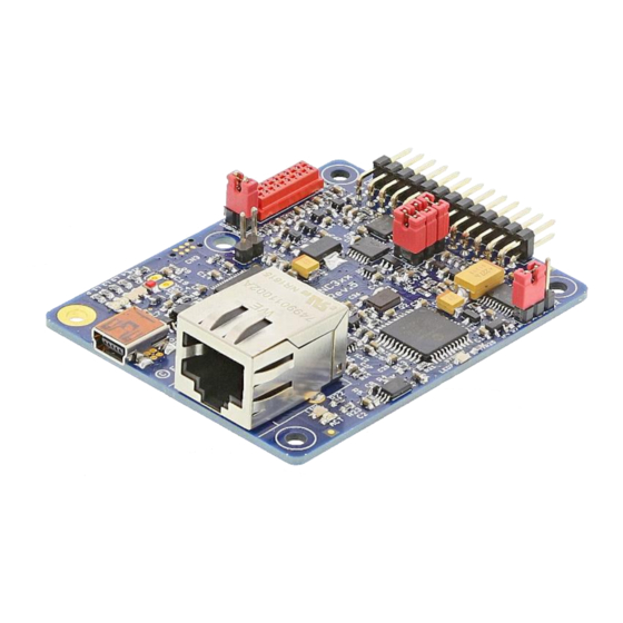
Page 5: Board Overview
Hardware Manual – CNC310 2 Board overview The CNC310 is a CNC controller with USB interface, and is intended for 3 axes. However, the user can upgrade the board through separate licenses with a 4 axis and activate the ethernet interface. -
Page 6: Board Jumpers And Indicators
Hardware Manual – CNC310 3 Board jumpers and indicators This chapter describes the jumpers and indicators that are present on the controller board. 3.1 Jumper USBPWR This jumper is used to power the board via the USB interface. The board can also be powered through an external pin. -
Page 7: Jumper Rdy/Pls
Hardware Manual – CNC310 3.3 Jumper RDY/PLS This jumper is used to set the output signal that is present on the I/O pin ‘WATCHDOG/SYSRDY‘. For more info see chapter 5.5 WATCHDOG/SYSRDY output Page | 7... -
Page 8: Jumper Jp1
Hardware Manual – CNC310 WATCHDOG/SYSRDY output. 3.4 Jumper JP1 This jumper can be used to deactivate the signals on some I/O pins. Currently make sure that all jumpers are mounted. Page | 8... -
Page 9: Power Led
Hardware Manual – CNC310 3.5 Power LED This blue power led indicates when power is applied to the board. 3.6 Status LED 1-4 The status LEDs indicate the current mode of the controller. The status LEDs are indicated by L1 through L4. -
Page 10: Network Leds (Optional)
Hardware Manual – CNC310 3.7 Network LEDs (optional) The network LEDs will only be active if the license has been activated for the network and new firmware has been downloaded. The LINK LED indicates if a network cable is connected. The ACTIVITY LED will blink if there is network communication. -
Page 11: Sysrdy Led
Hardware Manual – CNC310 3.8 SYSRDY led The LED indicates that status of the SYSRDY output. If it is ON, it indicates that the signal on the WATCHDOG/SYSRDY output also is active. Page | 11... -
Page 12: O Pinning
Hardware Manual – CNC310 4 I/O pinning 4.1 Pinning functions overview The board can be connected through a 26-pole header. The pitch of the connector is 2.54mm or 0.1”. The images below show the pin numbering and the functions on each pin. - Page 13 Hardware Manual – CNC310 In “Figure 3. Overview of functions.” all signals that are present are discussed in more detail. Name Direction Type Function Electrical Spec. Remarks TOOL DIGITAL Switching of tool TTL 5V/20mA DIR1 DIGITAL Direction signal X axis...
-
Page 14: Outputs
Hardware Manual – CNC310 5 OUTPUTS 5.1 TOOL output The TOOL output is used for switching ON and OFF the tool of your machine. The TOOL output is not cable of switching large loads. Therefor it will need a relay to switch large loads. - Page 15 This image shows how you can control a 5V or 24V (or almost any) relay with the output of the CNC310. It might be easier to find a board that has all logic already included on one board, and which can readily be found in the internet. Some will even include optocouplers.
-
Page 16: Coolant Output
5.4 AMP-ENABLE output The AMP-ENABLE output is used for enabling the motor drivers. This output can supply more output current than the other digital outputs. See also chapter 9 Example of connecting CNC310 to Leadshine DM422C. Page | 16... -
Page 17: Watchdog/Sysrdy Output
Hardware Manual – CNC310 5.5 WATCHDOG/SYSRDY output The WATCHDOG/SYSRDY can be used to indicate when the system is active. This can be either with a HIGH (active) / LOW (not active) signal or by outputting a square wave of 12 kHz. Often that signal is used as a kind of watchdog signal by for example stepper drivers. -
Page 18: Inputs
Hardware Manual – CNC310 6 Inputs This chapter describes how to use the inputs of the controller board. Make sure that the input signals do not exceed the maximum values of the input. 6.1 PROBE input The PROBE input has multiple functions, it can be used for:... -
Page 19: E-Stop Input
Hardware Manual – CNC310 If you need to connect multiple devices to this input, you can simply connect them in parallel, as shown in the image below. The system will know when to consider this an actual probe or when it is a toolsetter. -
Page 20: Home1 Input
Hardware Manual – CNC310 In the software it must be indicated whether a switch is either Normal-Open (NO) or Normal-Closed (NC). This is set via ‘Homing and E-Stop’ part of the setup screen. A message will appear onscreen to show that an E-STOP condition has occurred. -
Page 21: Home4 Input
Hardware Manual – CNC310 Figure 18. Connecting Normal-Open home switches in parallel. In the software it must be indicated whether a switch is either Normal-Open (NO) or Normal-Closed (NC). This is set via ‘Homing and E-Stop’ part of the setup screen. - Page 22 Hardware Manual – CNC310 Please note, that all home switches need to be the same with respect to Normal-Open or Normal- Close. Figure 20. Connecting switch to HOME4 input. In the software it must be indicated whether a switch is either Normal-Open (NO) or Normal-Closed (NC).
-
Page 23: Mpg/Pendant
Hardware Manual – CNC310 7 MPG/Pendant The MPG connectors makes it possible to directly connect a pendant to the controller. This option is only available if the full software is used. <TO BE ADDED> Page | 23... -
Page 24: Getting Started
Step 3. The board is now able to communicate with the application software. If you startup the software the board should be found. This is indicated by the controller type ‘CNC310’ appearing in the top-left of the window. If the board is not found it will show ‘SIMULATION’. - Page 25 Hardware Manual – CNC310 TIP: By using the software I/O screen you can manually control enabling the drivers. When the drive is not enabled you will be able to move the axis by hand, if it is enabled this should not be possible.
-
Page 26: Example Of Connecting Cnc310 To Leadshine Dm422C
Hardware Manual – CNC310 9 Example of connecting CNC310 to Leadshine DM422C. In the image below is drawing of how to simple the CN310 can be connected to a DM422C. Figure 21. Connecting CNC310 to Leadshine DM422C. Page | 26... -
Page 27: Mechanical Dimensions
Hardware Manual – CNC310 10 Mechanical dimensions The controller can simply be connected by using standard connector (2x13 pole), pitch 2.54mm/0.1”: For example: Wurth WR-PHD 613026243121 Page | 27...
Need help?
Do you have a question about the CNC310 and is the answer not in the manual?
Questions and answers