Table of Contents
Advertisement
Advertisement
Table of Contents
Troubleshooting

Related Manuals for CHART MVE Fusion


Summary of Contents for CHART MVE Fusion
- Page 1 MVE FUSION Technical Manual 20994124 REV A 1...
- Page 2 MVE Distributor or Service Technician. NOTE: All MVE Fusion models are Class I per IEC 61140, as the AC electrical supply requires a protective earth ground. These devices are externally powered and intended for continuous operation. The models are intended for professional use in research, while the medical device versions are intended to be used in situations that directly support medical applications.
- Page 3 Thermal gloves must be worn during indicated Gloves procedures. Wear a Face Shield A face shield must be worn during indicated procedures. ETL Listed Mark Chart Fusion Freezer conforms to UL STD 61010- 1 and certified to CSA STD C22.2#61010-1. 20994124 REV A 3...
- Page 4 1.782 lbs/L , 807.4 g/L , 808.6 kg/m3 Liquid Nitrogen Safety Transferring LN2 and operating the MVE Fusion should be done in accordance with the manufacturer/supplier instructions. It is important that all safety precautions recommended by the manufacturer be followed.
- Page 5 ). Chart Cryogenic Freezers must be installed and operated in well-ventilated areas. DO NOT vent container in confined spaces. DO NOT enter confined spaces where excess nitrogen gas may be present. If exposure has occurred move to ventilated area or fresh air. If breathing is difficult, supplement oxygen may be required.
- Page 6 Persons transferring LN2 should make every effort to protect the eyes and skin from accidental contact with liquid or cold vapor. Chart MVE recommends the following protective clothing and accessories when transferring LN2 or handling hoses, valves, and plumbing components: ...
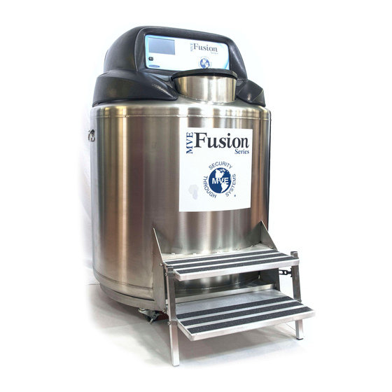
- Page 7 3 System Components and Function 3.1 System Overview The MVE Fusion system consists of several key components identified in Figures 1 and 2: dewar, Pressure Vessel, Liquefier, Shroud, Graphical User Interface (GUI), and Retractable Stairs. Figure 1: MVE FUSION FREEZER...
- Page 8 Figure 2: Cross Section of the MVE Fusion Freezer 20994124 REV A 8...
- Page 9 3.2 Liquefier The Liquefier contains the cryocooler and other support / interface control systems required to operate the MVE Fusion Freezer. Replacement of the liquefier should only be performed by a representative from Chart Inc. or trained authorized personnel. The Liquefier consists of the following major components and features: ...
- Page 10 Cooling Fans – Two 12 VDC, 150CFM fans with “CPU” style heat exchangers reject heat from the cryocooler and electrical components within the liquefier to the ambient environment. Alarms – In addition to the visual alarms displayed on the GUI, an alarm speaker is provided that sounds when any preset threshold (freezer temperature, low battery, motor temperature, VFD temperature, gas pressure, etc.) is exceeded or if the freezer lid has been removed for more than 5 minutes.
- Page 11 Figure 4: Internal Components of Liquefier Figure 5 : Liquefier back panel / Physical connections (Cowling off) 20994124 REV A 11...
- Page 12 3.3 Cryocooler The cryogenic cooler is the refrigeration device for the MVE Fusion. It is mounted on top of the MVE Fusion dewar. It provides cryogenic cooling by mechanically compressing and acoustically expanding the helium gas in a Stirling cycle. The base cryocooler unit consists of a pressure wave generator (PWG) and a coaxial Stirling (pulse tube) coldhead (see Figure 6).
- Page 13 Figure 7: Schematic cross section of Cryocooler The cryocooler system operates as follows (refer to Figure 7): 1. Helium gas is cyclically compressed and expanded relative to the mean pressure by the pistons of the PWG. 2. With each forward stroke of the pistons helium gas moves through the first warm heat exchanger (the “aftercooler”) where heat is removed.
- Page 14 Access Lid with Cork – Light, easily removable lid with magnetic switch that indicates when the lid has been removed or improperly placed. Storage Space – The MVE Fusion is designed with a rotating tray, lazy Susan, which allows access to all samples without difficulty.
- Page 15 Temperature Monitoring – An RTD is provided to monitor the upper storage space temperature and control the freezer operation. Cryogen Storage Pressure Vessel – 50-liter liquid nitrogen storage tank designed to ASME standards with safety pressure relief device and muffler. ...
- Page 16 Figure 9: Left to Right: Vent (Overfill) Valve, Relief Valve, and Fill Valve 20994124 REV A 16...
- Page 17 3.5 Pressure Vessel and Sample Storage Area The dewar is based on the Chart’s MVE High Efficiency Freezers, with modifications to incorporate a cryogen tank and cryocooler. The “lazy Susan” Carousel for sample racks is suspended from the neck of the cryogen tank and can be turned easily using the handles provided.
- Page 18 Figure 8. A restraint is included to keep the stairs from being accidentally unfolded. Transfer line – In the event the MVE Fusion needs refilling or topping off (for instance after a prolonged power outage) a proper hose to transfer LN2 from a supply tank to the pressure vessel is required.
- Page 19 The user’s probe must be small enough to navigate through a 0.3” ID conduit with a 4 inch-radius bend. If the Chart- supplied RTD has any issues or requires calibration, please contact Chart Industries or an authorized distributor.
-
Page 20: Product Specifications
(b) Additional temperature probe access tube for the secondary temperature probe 3.7 Product Specifications Table 2 : MVE Fusion Product Specifications Safety for Electrical Equipment ETL marked for use in the United States and Canada and Lab Use according to: UL 61010-1:2012 (Edition 3.0) - Page 21 Weight (Empty): < 750 lb (340 kg) Weight (Full): <1100 lb (500 kg) with 20 “13-2 large racks”, Liftover Height: 37.1 Inches (944mm) Electrical Power Power Adapter: Class I, 9A @ 120V, 60Hz Consumption: ~750 W (Maximum) Operating Conditions Temperature: 18°C – 27°C (65°F – 80 °F) Humidity: ≤50% (non-condensing) Pressure: 8.2 PSI (57.2 kPa) to 14.7 PSI (101 kPa) Standard Performance...
-
Page 22: Installation And Startup
Following the careful uncrating and unpacking of the freezer, install using these basic instructions. CAUTION: This information is included primarily for reference. Chart recommends any cryogen filling/refilling be done by Chart personnel or a Chart-authorized distributor. CAUTION: Always wear protective gloves and face shield when work in with liquid nitrogen. - Page 23 Error! Reference source not found. for a standard Fusion rack layout. NOTE: VERY IMPORTANT TO ADD RACKS AND BOXES BEFORE FILLING. Figure 13: (a) View inside storage container, (b) Inventory systems Figure 14: Rack Layout for MVE FUSION 20994124 REV A 23...
- Page 24 (i.e. the pressufe relif valve (PRV) venting downwards). 4. Insert the other end of the transfer hose into the Fusion dewar storage space. Chart recommends that a phase separator be placed on this end of the transfer hose for this filling process.
- Page 25 Figure 16: Isolation valve; (a) Open state, (b) Close state 9. Open the liquid supply valve on the 230 liter LN2 supply tank. 10. Open the vent valve on the Fusion (refer to Error! Reference source not found.). This will prevent over pressurization and lifting the relief valve during the filling process.
- Page 26 13. Open both isolation valves located underneath the shroud (refer to Figure 16). 14. Connect the supplied A/C electrical power cord to MVE Fusion power receptacle at the rear (see for Section 5 further details on system powering). Figure 18: AC power supply...
- Page 27 operation. Be prepared to have a 230 LN2 cylinder @ 22-35 PSI to refill pressure vessel if this occurs. 20994124 REV A 27...
-
Page 28: Basic Operation
5.1 Basic Operation The MVE Fusion is a “self-sustaining” cryogenic storage freezer which normally requires limited user intervention once it has been installed at the customers site and Chart (or an authorized distributor) performs the first fill. However, there are circumstances (power outages, for instance) when the system will require attention. - Page 29 Figure 19 : Main and Battery Backup power switches 3. Once powered on, the MVE Fusion controller will start up with two screens displaying the Android logos shown in Figure 20 before the main menu of the Fusion application is loaded.
- Page 30 5.2 Operating the Android User Interface 5.2.1 Navigating the GUI There are several screens available within the fusion android application to monitor the system performance and doing specialized tasks such as resetting alarms or changing the system password. To reach other screens within the app, swipe sideways with a finger, or touch the tabs in the upper left-or right-hand corners of the screen the user is in.
- Page 31 Figure 21: Graphical User Interface Main Screen 1. Current Time and Date – The user can update the Time and date by tapping on the top right-hand corner. 2. Freezer Temp – Temp A equals the air temperature at or near the “top box” level of standard storage racks.
- Page 32 5. Speaker toggle button- This button renders the speaker silent for non-alarm sounds. Temperature Timeline – This sub window displays the time vs RTD temperature. It has the capacity to display the data for the selected day or a week or even a month.
- Page 33 5.2.4 Calibration Screen The “Calibration” screen is for calibrating the built in RTD that comes with the MVE Fusion (see Figure 23). As mentioned earlier, the user does not normally use this feature. This product has the two-point calibration capability.
- Page 34 5. Submerge both probes into LN2 or an ice bath, depending on the type of calibration being performed. The temperature values displayed are raw data (meaning they are very sensitive and will change very quickly), so wait for the values to stabilize before proceeding to the next step.
- Page 35 Figure 24 : (a) Format of the Data logs screen, (b) Format of the Data file 20994124 REV A 35...
- Page 36 5.2.6 Settings Tab This tab provides the capabilities of changing the password, resetting the password, and several other options. Password changing process is given below; 1. Select the “Password” screen. 2. Enter the current password in the “Current Password” field. 3.
- Page 37 5.3 Routine Operation Under Normal Operation, the MVE Fusion Freezer operates without any user intervention. The user has simply to load (Precooled) or remove samples from the storage space as desired. Nonetheless, there are a few guidelines that will result in the most successful operation.
-
Page 38: Preventative Maintenance
5.4 Shutdown MVE Fusion Switch off the Main Power and Battery backup to shut down the MVE Fusion unit. Remove the input power cable to isolate from the wall outlet. There is no system shutdown option in firmware. - Page 39 1. Liquid Level can only be verified via the GUI. Verification Lid Inspection 1. Remove the lid slowly from the MVE Fusion. 2. Inspect lid for any damage and replace parts if necessary 1. Remove the lid slowly from freezer.
- Page 40 4. Trim to size as needed. Refill Pressure 1. Please refer to Section 5.1 Filling the MVE Fusion on Vessel how to fill the inner vessel of the MVE Fusion. Chart Authorized person should only carried out this activity.
- Page 41 Figure 26: After removing the Screws on the liquefier 4. Take a cloth and wipe away any dust or debris off the two fans. CAUTION: Ensure that the LN2 supply valve is closed and the plumbing assembly is vented before removing the relief valve.
- Page 42 lead to a dangerous over pressurized condition. Additionally, this will void any warranty. 1. Unplug the main power and battery backup if equipped. 2. Open or remove lid from freezer. 3. Open the vent valve Allow LN2 to completely evaporate and the freezer space to warm to room temperature.
- Page 43 constantly monitor, charge, and sense the current in its battery circuit. With its main power connected, the GUI will constantly produce a 27 VDC trickle charge to keep the batteries fully charged. INTERNAL BATTERY REPLACEMENT PROCEDURE 1. Make sure the power supply and the battery backup are disconnected.
- Page 44 Figure 27: Battery Backup MVE Fusion firmware should only be updated by authorized Firmware Chart personal or MVE Distributors. Improper firmware Updates updates can render the controller inoperable. Please contact Chart Technical Service for further details. 20994124 REV A 44...
- Page 45 On/Off Switch 21183303 Battery Backup Assembly 5.7 End of Life Disposal The Fusion freezer should be returned to Chart at the end of its useful life for proper disposal. Please contact a Chart to discuss arrangements. 20994124 REV A 45...
- Page 46 The data streams on the RS232 ports can be accessed by a command-line terminal application such as TeraTerm. Please contact Chart or an authorized representative to connect to these ports (passwords are required to access the data or make changes to parameters).
- Page 47 Table 6: Alarm parameter ranges Set Points Define by Parameter HIGH Temperature User can adjust HIGH Freezer -150 °C No limit Alarm value but limited to -160 °C -170 °C Alarm No limit System Tip Temperature 50 °C Reject Temperature No limit System 50 °C...
- Page 48 MOTOR R OUT OF Right motor out of Consult technical manual or contact service RANGE range technician. TIP TEMP OUT OF Tip temp. out of Consult technical manual or contact service RANGE range technician. REJECT T OUT OF Reject temp. out of Consult technical manual or contact service RANGE range...
-
Page 49: Troubleshooting
6.4 Troubleshooting CAUTION: This information is included primarily for reference. Chart recommends any advance troubleshooting or RTD calibration be done by Chart personnel or a Chart-authorized distributor. 20994124 REV A 49... - Page 50 NOTES: 20994124 REV A 50...
- Page 51 20994124 Rev A Chart Inc. reserves the right to discontinue its products, or change the prices, materials, equipment, quality, descriptions, specifications and/or processes to its products at any time without prior notice and with no further obligation or consequence. All rights not expressly stated herein are reserved by us, as applicable.
Need help?
Do you have a question about the MVE Fusion and is the answer not in the manual?
Questions and answers