Table of Contents
Advertisement
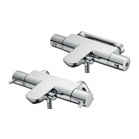
Thermostatic Bath Shower Mixers
ALTO ECOTHERM
Exposed two hole thermostatic bath shower mixers in this product range are:
A5634AA Wall mount mixer with fast fix bracket
A5635AA Mixer with rim mount legs
A5636AA Mixer with rim mount legs and Idealrain S3 (3 function) Shower Kit Pack
A5638AA Mixer with rim mount legs and lever handles
A5639AA Wall mount mixer with fast fix bracket and lever handles
BEFORE CONNECTION, FLUSH WATER
THROUGH PIPEWORK TO REMOVE ALL
DEBRIS ETC. WHICH COULD
DAMAGE THE VALVE MECHANISM
Installation Instructions
IMPORTANT
INSTALLER
After installation please pass
this instruction sheet to user
Advertisement
Table of Contents

Related Manuals for Ideal-Standard ALTO ECOTHERM A5634AA


Summary of Contents for Ideal-Standard ALTO ECOTHERM A5634AA
- Page 1 Installation Instructions Thermostatic Bath Shower Mixers ALTO ECOTHERM Exposed two hole thermostatic bath shower mixers in this product range are: A5634AA Wall mount mixer with fast fix bracket A5635AA Mixer with rim mount legs A5636AA Mixer with rim mount legs and Idealrain S3 (3 function) Shower Kit Pack A5638AA Mixer with rim mount legs and lever handles A5639AA Wall mount mixer with fast fix bracket and lever handles IMPORTANT...
-
Page 2: Table Of Contents
TABLE OF CONTENT 1 DIMENSIONS ................3 2 INTRODUCTION ................. 6 3 SUPPLY CONDITIONS ..............7 4 PRE-INSTALLATION NOTES ............8 4.1 INSTALLING PANEL/WALL MOUNT PRODUCTS ........9 4.2 INSTALLING RIM MOUNT PRODUCTS ............ 12 5 OPERATION ................13 6 MAXIMUM TEMPERATURE STOP ..........14 7 CALIBRATION OF THERMOSTAT .......... -
Page 3: Dimensions
1 Dimensions A5634AA Bath shower mixer with wall mount bracket A5635AA Bath shower mixer with rim mount legs... - Page 4 max.305 G1/2 male A5636AA Bath shower mixer with rim mount legs and Idealrain S3 shower kit pack Ø44 22° G1/2 max.35 G3/4 For guidance on how to install the shower kit, please refer to the separate instructions provided with the kit.
- Page 5 A5638AA Bath shower mixer with rim mount legs and lever handles A5639AA Bath shower mixer with wall mount bracket and lever handles...
-
Page 6: Introduction
The fittings covered by these instructions should be installed in accord- ance with the Water Regulations published in 1999*. Ideal Standard strongly recommends that these fittings are installed by a professional fitter. *A guide to the Water Supply (Water Fittings) Regulations 1999 and the Water Byelaws 2000, Scotland is published by WRAS (Water Regulations Advisory Scheme) Unit 13, Willow Road, Pen-y-Fan Industrial Estate, Crumlin, Gwent, NP11 4EG. -
Page 7: Supply Conditions
3 SUPPLY CONDITIONS Table 1 Conditions of use for Type 2 valves BSEN1111 Operating pressure range: High Pressure Maximum static pressure 10 bar Flow pressure hot and cold 0.5 to 5.0 bar Hot supply temperature 55 to 65 °C Cold supply temperature 5 to 20 °C Temperature differential characteristic (TDC) 10 °C... -
Page 8: Pre-Installation Notes
4 Pre-installation notes This installation instruction covers two main products types: wall mount and rim mount. Products within this range can be installed either on a panel/wall over a bath or on the rim of a bath. • Panel/wall mount products are: A5634AA & A5639AA. •... -
Page 9: Installing Panel/Wall Mount Products
4.1 Installing panel/wall mount products The thermostatic mixing valve must be installed in such a position that maintenance of the TMV and its valves and the commissioning and testing of the TMV can be undertaken. IMPORTANT BEFORE CONNECTION, FLUSH WATER THROUGH PIPEWORK TO REMOVE ALL DEBRIS ETC. - Page 10 Note: Tile closely to the pipe to ensure gasket Palce gasket on the rear of wall mount plate effectiveness Tighten up the two screws until secure. Note: For plaster board duct it will be ne- cessary to fit extra strong cavity an- chor plasterboarad fixings as shown.
- Page 11 Fit the olives to the pipes prior to Fit 15mm screwing the two 3/4“ connectors Olives x2 into the wall mount plate using a 1/2“ allen key. The connectors will have to be secu- rely screwed in to form the neces- 1/2“...
-
Page 12: Installing Rim Mount Products
4.2 Installing rim mount products The thermostatic mixing valve must be installed in such a position that maintenance of the TMV and its valves and the commissioning and testing of the TMV can be undertaken. IMPORTANT BEFORE CONNECTION, FLUSH WATER THROUGH PIPEWORK TO REMOVE ALL DEBRIS ETC. -
Page 13: Operation
5 Operation ATTENTION: TEMPERATURES HIGHER 40°C CAN BE HARMFUL TO YOUR HEALTH. Lever handle products Right handle controls water flow rate • This handle is shown above parked in the off position. • Rotating this handle downwards commences water flow. By rotating the handle 90° from the off position the user will encounter economy flow “stop”... -
Page 14: Maximum Temperature Stop
6 Maximum temperature stop 40˚C 104°F The water temperature up to the stop but- ton on the handle is set at 40°C. The maximum mixed water temperature 43˚C (achieved by overriding the stop button on 109°F the handle) is factory set at 43°C. To change this temperature, remove the temperature control handle, see 8. -
Page 15: Commissioning & Periodic Checks
7.1 Commissioning & periodic checks. The following procedures should be carried out after installation and every 12 months after to ensure that the valve is functioning correctly. Check that: 1. The application of the thermostatic valve matches the approved designation. 2. -
Page 16: Thermostatic Cartridge Replacement
8 Thermostatic cartridge replacement The thermostatic cartridge seldom fails and the possibility of blocked filters should be investigated be- fore contemplating replacing it. Small particles of water borne debris may still find their way onto the filter screens on the thermostatic cartridge. These should be cleaned and re-fitted. To replace the thermostatic cartridge: 1. -
Page 17: Flow Cartridge Replacement
8 Thermostatic cartridge replacement cont’ 5. Unscrew cartridge with a 24mm A/F deep socket, expect some trapped water to escape. Replace the cartridge if necessary. When refitting cartridge, do not over tighten, hand tighten the first few threads, maximum torque 16Nm. lubricate o-rings before... -
Page 18: Diverter Cartridge Replacement
9 Flow cartridge replacement cont When refitting cartridge, do not over tighten, hand tighten the first few threads, maximum torque 12Nm. FOR LEVER HANDLE VERSIONS: 1. Unscrew dog point screw and pull off temperature control handle. 2. Remove handle screw. 3. -
Page 19: Check-Valve Replacement
11 Check-valve replacement Check valves are located in both (hot & cold) inlets to the mixer. To replace the check valves: 1. Seperate the shower valve from the wall bracket by undoing the captive nuts. See sect.4.1 step 9. Use 30mm A/F spanner. 2. -
Page 20: Spare Parts
13 Spare parts A5634AA... - Page 21 A5635AA & A5636AA...
- Page 22 A5638AA...
- Page 23 A5639AA...
-
Page 24: Cleaning Chrome Plated Surface
When cleaning the shower valve always use soap based cleaners. Never use abrasive or scouring powders and never use cleaners containing alcohol, ammonia, nitric acid, phosphoric acid, organic solvents or disinfectants. Ideal Standard pursues a policy of continuing im- CUSTOMER CARE HELP LINE provment in design and performance of its products.
Need help?
Do you have a question about the ALTO ECOTHERM A5634AA and is the answer not in the manual?
Questions and answers