Advertisement
Quick Links
Advertisement

Related Manuals for Lefroy Brooks CT 8700


Summary of Contents for Lefroy Brooks CT 8700
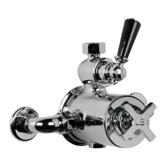
- Page 1 CT 8700 / MK 8700 EXPOSED THERMOSTATIC SHOWER VALVE WITH CERAMIC LEVER INSTALLATION GUIDE...
- Page 2 DIMENSIONS Shown with CT8700 105mm 33mm 15mm Copper 107mm Ø90mm 153mm (Connaught – CT) 148mm (Mackintosh – MK) G¾ 50mm COLD MADE IN 200mm Not to scale...
- Page 3 TYPICAL SHOWER SETS All dimensions are taken from centres 585mm COLD 1035mm 200mm maximum 1085mm maximum CT/MK 8705 COLD COLD 200mm 585mm 200mm 200mm COLD CT/MK 8703 CT/MK 8702 CT/MK 8720 (Note: On 8720 the hot is on the right and cold on the left) Not to scale...
-
Page 4: Exploded View
EXPLODED VIEW PTE007 – Pair of 15mm crack cover plates PTE006 – Pair of 15mm inlet connection elbows PTE040 – A single 15mm crack cover plate with compression nuts, olives and fibre washers PTE041 – A single 15mm inlet connection elbow with compression nut, olive and fibre washer PTS004 –... - Page 5 TYPICAL FLOW RATES Flow (Litres/minute) Note: Balanced pressures shown are applied directly to the hot and cold inlets; flow rates indicated are free flowing and may vary subject to restrictions created by installation, pipework, layout or application. The outlet temperature during testing was 38°C.
- Page 6 The hot water supply must be connected to the Suits all systems left inlet elbow and cold water supply to the This Lefroy Brooks product is potentially right inlet elbow, as viewed from the front. If the suitable for every possible application, type of thermostatic valve is fitted with the flow valve boiler and water supply pressure.
- Page 7 Fixing the valve backplate to a wall Access When locating and securing the valve backplate It is important to leave suitable clearance and (see exploded view) to a wall, it is important access to the valve and connections for future to use No.
- Page 8 SETTING ‘SAFE TEMPERATURE’ Recommended safe temperature settings: General domestic: 38 °C Young children or elderly: 37 °C For specific details please refer to local building regulations, current legislation, relevant standards and codes of practice. This valve is designed to be set at the required safe operating temperature, but is fitted with an override button which allows the user to select higher temperatures if required.
- Page 9 FITTING THE ‘TEMPERATURE OVERRIDE’ Once the safe operating temperature has been set, the next stage is to correctly assemble the temperature stop (D) & override (C). The temperature stop and ‘safe temperature’ button can be positioned to customer requirements. The below setting is suitable for right handed operation. Three typical settings are shown on the next page.
- Page 10 The temperature stop and safe temperature button can be positioned to customer requirements as below: Button position Temperature stop position Safe temperature (see ‘setting safe temperature’ section) Minimum temperature Set horizontal – or slightly lower (button alignment) MADE IN Maximum temperature Safe temperature button set to left (suitable for right handed operation)
- Page 11 SERVICING THE THERMOSTATIC CARTRIDGE If after a period of time you experience temperature problems with your shower valve, particularly if you are in a hard water area, it is quite common for limescale deposits to have formed in the thermostatic cartridge. We recommend you remove the cartridge and soak it in a descaling fluid which normally resolves the problem.
- Page 12 5 Check the ‘o’ rings (L) for damage (ie. cuts or tears). Remove the ‘o’ rings before soaking the cartridge in descaling fluid. Soak the cartridge according to the instructions on the descaling fluid packaging. Rinse under cold water before fitting (refer to the ‘installing the thermostatic cartridge’ section to install). INSTALLING THERMOSTATIC CARTRIDGE Slot Groove...
- Page 13 REPLACING THE FLOW CARTRIDGE If after a period of time you experience problems with your shower or hand shower developing a regular drip after use, it is normally an indication that the flow cartridge requires replacement. (PTE002) 1 Remove the lever assembly (M) by fully 3 Using a 17mm spanner or socket, unscrew unscrewing and removing the fulcrum screw the flow cartridge (R) (counterclockwise) and...
- Page 14 REPLACING THE NON-RETURN VALVES Non-return valve (NRV) 1 Isolate the hot and cold water supplies before 3 Unscrew the elbow assemblies from the sides the shower valve. Unscrew and remove the of the thermostatic valve body. hose/pipe connected to the flow valve outlet. Unscrew the three set screws from the valve backplate.
- Page 15 DON’Ts • Check all joints and connections. • Do not use excessive force when turning • Ensure that the ‘safe temperature’ has been set. the thermostatic cartridge spindle. This will • Ensure the black plastic ‘temperature stop’ has damage the cartridge. To avoid damage, when been fitted to avoid damage to the thermostatic setting the ‘safe temperature’...
-
Page 16: Customer Support
20.065.272A / JUNE 2017 CUSTOMER SUPPORT +4 4 (0)1992 70 8 316 L E F R O Y B R O O K S . C O . U K Whilst every effort is made to ensure the accuracy of these, they are subject to change without notice as part of the company’s product development process.
Need help?
Do you have a question about the CT 8700 and is the answer not in the manual?
Questions and answers