
Summary of Contents for CenterLine VeriFast LVDT
- Page 1 c o n n e c t i n g n e e d s w i t h c a p a b i l i t i e s VeriFast LVDT User Manual Ver. 1.15 – September 2018 FDP-VFA-LVD-UM-EL-1.15-0918...
-
Page 2: Product Sales And Support
Product Sales and Support ™ The VeriFast LVDT is a component of a resistance welding system manufactured by: For all replacement parts and service inquiries, contact CenterLine’s inside sales department: Telephone: 519.734.8330 Fax: 519.734.2006 Toll Free in Canada & US: 1.800.268.8330... - Page 3 In no event will CenterLine (Windsor) Limited be responsible or liable to any party for any personal injury, property or other damages of any nature whatsoever, whether special, direct, indirect, incidental, consequential or compensatory, directly or indirectly resulting from the publication, use of, or reliance on this document, and also from the use of the equipment described herein.
- Page 4 This page is left blank intentionally.
-
Page 5: Table Of Contents
Safety Information ............................... 9 Important Safety Information ........................9 Handling the VeriFast LVDT ......................... 9 Potential Hazards Related to VeriFast LVDT ..................... 10 Personal Protective Equipment ........................10 Equipment and Process Overview ........................11 Intended Use of Equipment ........................11 VeriFast LVDT Main Components ...................... - Page 6 Connecting the Signal Conditioner to the 5-pin Shielded Cable and PLC ......... 22 Synchronizing Multiple Signal Conditioners ..................22 Connecting the 5-pin Shielded Cable/Connector to the VeriFast LVDT Electrode ......22 Learning about the VeriFast LVDT Signal Conditioner ................23 Operation of LED Indicators .......................
-
Page 7: Preface
Preface Who Should Use This Manual Any person installing, using, or maintaining a VeriFast LVDT unit should use this manual. Purpose of This Manual This manual describes the function, installation and necessary operating instructions for the proper use of the standard VeriFast LVDT. For assistance with any other customized products or non-standard applications, additional support is available from CenterLine. -
Page 8: Terminology And Symbols Used Throughout This Manual
Terminology and Symbols Used Throughout This Manual Throughout this manual, all the safety related notes have been identified by the following terms: This symbol relates information about practices or situations that can lead to personal injury or death, property damage, or economic loss. Attention statements help you to: •... -
Page 9: Safety Information
The VeriFast LVDT is used in conjunction with welding equipment and machinery. Therefore, as a supplement to the safety information offered in this manual for the VeriFast LVDT, all the safety considerations that pertain to the equipment used in conjunction with the VeriFast LVDT still apply and must be followed thoroughly. -
Page 10: Potential Hazards Related To Verifast Lvdt
Potential Hazards Related to VeriFast LVDT The VeriFast LVDT system has no specific hazards related to it. However, as the VeriFast LVDT is used in conjunction with other equipment such as welding equipment and machinery, robot, air supply, etc., the user should be aware of the warnings, hazards, and precautions related to the use of the equipment as a whole. -
Page 11: Equipment And Process Overview
The VeriFast LVDT is a component of a resistance welding system. When properly installed in conjunction with resistance weld control equipment and used within the system’s specification limits, the VeriFast LVDT is used to verify the presence and orientation of fasteners or materials. The VeriFast LVDT is not intended for any other use. -
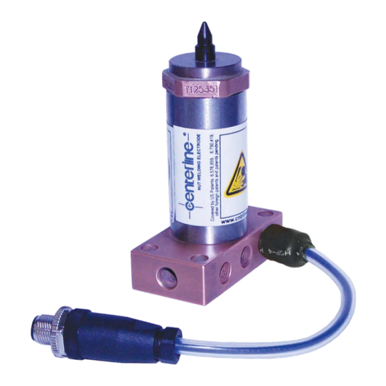
Page 12: Verifast Lvdt Main Components
Figure 1 – Nut Detection and Orientation VeriFast LVDT Main Components The VeriFast LVDT has a robust construction that allows for fast and easy component changes. A standard configuration of VeriFast LVDT is illustrated in Figure 2 below. Figure 2 – VeriFast LVDT Configuration VeriFast LVDT –... -
Page 13: Verifast Lvdt Configurations
VeriFast LVDT Configurations Base Mount Styles (Except SXZR) VeriFast LVDT – User Manual – FDP-VFA-LVD-UM-EL-1.15-0918... -
Page 14: Syvr Extended Base Mount Style
SYVR Extended Base Mount Style SXZR Base Mount Style VeriFast LVDT – User Manual – FDP-VFA-LVD-UM-EL-1.15-0918... -
Page 15: Tapered And Threaded Mount Styles
Tapered and Threaded Mount Styles Clamp Mount Style VeriFast LVDT – User Manual – FDP-VFA-LVD-UM-EL-1.15-0918... -
Page 16: Part Ordering Information
If you need to order other components, please refer to the detailed VeriFast LVDT Part Ordering Instructions brochure available from CenterLine. For optimal equipment performance and full warranty support, CenterLine consumables must be used. -
Page 17: Required Services
Control Requirements Minimum recommended control connection requirements are as follows: An analog input is required to receive the VeriFast LVDT system signal and a 15 bit resolution is recommended to achieve ideal operating performance. Actual performance is dependent on the effective resolution of the control system to which the VeriFast LVDT system is integrated. -
Page 18: Water Supply Requirements
Water Supply Requirements The welding equipment requires water cooling to dissipate the heat generated in the resistance welding process. The operating performance of the equipment is closely tied to the quality and configuration of the water supply system. • Improper water hookup will result in insufficient cooling, which may cause severe equipment damage or personal injury. -
Page 19: Installation Guidelines
Pre-Installation Tips and Requirements Before starting to install the VeriFast LVDT, please be aware of the following: • If replacing older ‘legacy’ bodies, the mounting hole pattern of the VeriFast™ LVDT will be different than the existing hole pattern. An adapter plate may be required to mount the LVDT body, as the new mounting holes would be drilled too close to the existing ones. -
Page 20: Mounting The Base Mount Electrode
Mounting the Base Mount Electrode The weld electrode’s mounting on industrial equipment (e.g., platen, sub-plate, etc.) is usually a copper-to-copper contact surface that will transfer current; therefore, both surfaces need to be clean and free from oil, dirt, and any other contaminants. Any contamination will increase the resistance of the joint, which in turn causes less current to flow and, therefore, an increase in temperature will result. -
Page 21: Mounting The Signal Conditioner
The Signal Conditioner is configured to be mounted on a standard DIN rail. Wiring the VeriFast LVDT and Signal Conditioner Use a 5-pin shielded cable to establish the connection between the VeriFast LVDT Electrode and Signal Conditioner (see Figure 3 below). Use separate wiring (not shown) to connect the Signal Conditioner to the PLC. -
Page 22: Connecting The Signal Conditioner To The 5-Pin Shielded Cable And Plc
When multiple Signal Conditioners are mounted in close proximity to each other, interference may occur between them because of differences in excitation frequency. This interference may produce noise on the voltage outputs. In order to prevent this from occurring, the VeriFast LVDT Signal Conditioners must be synchronized with each other. -
Page 23: Learning About The Verifast Lvdt Signal Conditioner
Learning about the VeriFast LVDT Signal Conditioner Operation of LED Indicators The VeriFast LVDT Signal Conditioner is shown in Figure 4 to the right. The mode of operation for the LED indicators is explained in Table 3 that follows. For a complete list of all Signal Conditioner electrical connections and technical specifications, please refer to Appendix A on page 44. -
Page 24: Re-Calibrating The Signal Conditioner (If Necessary)
Re-Calibrating the Signal Conditioner (If necessary) When delivered to the customer, the VeriFast LVDT is fully calibrated for use with a 22 mm weld pin stroke. If a 50 mm weld pin stroke is being used, or if, for any other reason, you suspect that your equipment needs to be recalibrated, follow the instructions below. -
Page 25: Establishing The Pneumatic Service Connection
(0.0000264”), the 10 mV noise level would still limit practical resolution to 0.022 mm (0.00087”). Establishing the Pneumatic Service Connection The primary function of the compressed air supplied to the VeriFast LVDT is to control the actuation of the weld pin. Based on the Pin type (i.e., Retractable or Non-Retractable), type of application (e.g., nut/stud welding, welding ring projections, clinching applications) and the... -
Page 26: Pneumatic Connection Diagram For Lvdt Weld Bodies With Retractable Pin (Not Applicable To Clamp Mount Assemblies)
CenterLine recommends using a 3-position center open valve to extend and retract the weld pin. The center open position reduces air consumption when the valve is de-energized. CenterLine also recommends using a 3-port shuttle valve to ensure continuous air blow off in all pin positions. -
Page 27: Pneumatic Connection Diagram For Lvdt Weld Bodies Used In Ring Weld Or Clinching Applications (Not Applicable To Clamp Mount Assemblies)
Pneumatic Connection Diagram for LVDT Weld Bodies Used in Ring Weld or Clinching Applications (Not applicable to Clamp Mount Assemblies) Figure 7 – Pneumatic Connection Diagram for LVDT Weld Body Used in Welding Ring Projections or Clinching Applications (Not applicable to Clamp Mount Assembly) Pneumatic Connection Diagram for LVDT Weld Bodies with Non-Retractable Pin (Not applicable to Clamp Mount Assemblies) For proper operation, the AIR UP Regulator must be set at a higher pressure than the AIR... -
Page 28: Pneumatic Connection Diagram For Lvdt Clamp Mount Weld Bodies With Retractable Pin
Pneumatic Connection Diagram for LVDT Clamp Mount Weld Bodies with Retractable Pin Figure 9 – Pneumatic Connection Diagram for LVDT Clamp Mount Weld Body (Only) with Retractable Pin Pneumatic Connection Diagram for LVDT Clamp Mount Weld Bodies with Non-Retractable Pin Figure 10 –... -
Page 29: Maintenance
Important: For SXZR and Clamp Mount styles, please see the sections that follow. Although the VeriFast LVDT unit is a sealed, low maintenance device, the Weld Pin and the Electrode Head need to be replaced at regular intervals. In addition, by following the procedure illustrated below, other internal components can be inspected and/or replaced as needed. - Page 30 Step 2 Remove the used Weld Pin and Connecting Rod Assembly from the Electrode Body. Step 3 If the Connecting Rod and Pin Lock are in good Connecting Rod shape, they can be disassembled from the used weld pin and reused with a new Weld Pin. Pin Lock To start this procedure, install the used pin upside down in a vise (see picture on the right).
- Page 31 Step 6 With the protective wrap on the pin, place the new Weld Pin upside down into the vise. New Weld Pin with Protective Wrap Step 7 Apply LOCTITE 243 THREADLOCKER (blue colour) to threads on Pin Lock. Apply to both internal and external threads.
- Page 32 Step 10 Apply a small amount of grease to the O-ring on the Weld Pin (Note: Magnalube-G grease is recommended). O-ring Step 11 Remove the Weld Pin from the vise and discard the Protective Wrap. Insert the new Pin/Connecting Rod Assembly into the Electrode Body.
-
Page 33: Servicing The Lvdt Electrode Assembly For Sxzr Base Mount Style
Servicing the LVDT Electrode Assembly for SXZR Base Mount Style Although the VeriFast LVDT SXZR Base Mount Assembly is a sealed, low maintenance device, the Weld Pin and the Electrode Head need to be replaced at regular intervals. In addition, by following the procedure illustrated below, other internal components can be inspected and/or replaced as needed. - Page 34 Step 5 LVDT Cable If the LVDT Cable Assembly and Pin Lock are in good shape as shown in the previous step, they can be disassembled from the used Weld Pin Lock Pin and reused with a new Weld Pin. To start this procedure, install the used Weld Pin upside down in a vise and continue with Step 6 below.
- Page 35 Cable Assembly E-Clip Disk Step 9 Slide the Pin Lock (sunken side first) onto the Cable Assembly. Ensure that the E-Clip Disc fits properly into the sunken area of the Pin Lock. Sunken Area on Pin Lock Step 10 Orient the Cable Assembly downward so that the E-Clip Disk stays seated into the sunken area of the Pin Lock.
- Page 36 Step 12 Carefully thread the Pin Lock (with the Cable Assembly) onto the base of the Weld Pin, being careful not to cross the threads. Very important: After the procedure, check that the Pin Lock and the LVDT Cable are tight and do not move or rotate relative to the Weld Pin.
-
Page 37: Servicing The Lvdt Electrode Assembly For Clamp Mount Style
Servicing the LVDT Electrode Assembly for Clamp Mount Style Although the VeriFast LVDT Clamp Mount Assembly is a sealed, low maintenance device, the Weld Pin and the Electrode Head need to be replaced at regular intervals. In addition, by following the procedure illustrated below, other internal components can be inspected and/or replaced as needed. - Page 38 Step 4 Remove the weld pin from the piston rod. If only the Pin and Head need to be replaced, the procedure ends here. To install a new Pin and Head, skip directly to Step 9 on page 39, then finish by reversing the steps performed to this point (Step 4 to Step 1).
- Page 39 Step 7 Remove the piston rod assembly. Step 8 Replace and lubricate O-rings if required. Note: Magnalube-G grease is recommended for lubrication of O-rings and piston rod shaft. Step 9 Inspect all components for wear and replace as needed. Assemble all components in reverse order, manually lowering the pin to ensure that the connecting rod properly aligns/inserts into the LVDT coil.
-
Page 40: Working Area Maintenance
Excessive contamination and buildup reduce the performance accuracy and service life of the VeriFast. A routine examination of the VeriFast LVDT should be performed on a regular basis to verify that all connections are tight and in good order. -
Page 41: Troubleshooting Quick Guide
• Before turning ON the equipment, make sure all components are assembled properly. To troubleshoot the VeriFast LVDT unit, please refer to Table 4 that follows. VeriFast LVDT – User Manual – FDP-VFA-LVD-UM-EL-1.15-0918... - Page 42 Table 4 – Troubleshooting the VeriFast LVDT Hint Suggestion Problem Confirm that the connection of the cable is fastened completely and firmly. Check the cable between the VeriFast LVDT Is the VeriFast LVDT Power ON, but no unit and network connection for damage or...
-
Page 43: Decommissioning
• Disconnect the VeriFast LVDT system from the external supplies (electrical, air) and identify the connections to facilitate a future installation. • The storage location must be clean, dry, and not expose the VeriFast LVDT system to mechanical or thermal damage. If the VeriFast will be covered, there should be some air circulation to prevent condensation. -
Page 44: Appendix A - Signal Conditioner Specifications
Appendix A – Signal Conditioner Specifications Complete Signal Conditioner Electrical Connections Color Terminal Name Function SYNC I/O Synchronization (Daisy chain for multiple units) ERROR DOUT* Error Flag Output White Primary Coil 1 Primary Excitation to LVDT Primary Coil 2 Primary Excitation to LVDT SHIELD** Optional cable Shield connection NULL DOUT*... - Page 45 Should you have any questions after reading this User’s Manual, please feel free to contact your CenterLine representative. Please refer to the inside front cover of this manual for CenterLine contact information). VeriFast LVDT – User Manual – FDP-VFA-LVD-UM-EL-1.15-0918...
- Page 46 This page is left blank intentionally. VeriFast LVDT – User Manual – FDP-VFA-LVD-UM-EL-1.15-0918...
-
Page 47: Index
Pneumatic for LVDT Weld Bodies with Wiring, 21 Retractable Pin, 26 Wiring to Signal Conditioner, 21 Pneumatic for Weld Ring Projections Wiring to VeriFast LVDT Electrode, 22 Applications, 27 Control Requirements, 17 Base Mount LVDT Electrode, 13 Mounting, 20 Decommissioning, 43... - Page 48 Detection and Orientation, 12 Correct Orientation, 12 Upside Down Condition, 11 Detection and Orientation, 12 Error Detected Conditions, 12 Part Ordering for VeriFast LVDT, 16 Hazards Pneumatic Potential Hazards, 10 Connection for Clinching Applications, 27 Connection for LVDT Clamp Mount Weld...
- Page 49 Pneumatic Supply Requirements, 17 No Fastener Detected, 11 Service Connection, 25 No Part Detected, 11 Nut is Upside Down, 11 Pre-Installation Weld Complete, 11 Requirements, 19 Weld Pin Extended Position, 11 Tips, 19 Weld Pin Retracted Position, 11 Process Overview, 11 Weld Proceed, 11 Signal Conditioner Complete Electrical Connections, 44...
- Page 50 Signal Conditioner to PLC, 22 Wiring, 21 the 5-pin Shielded Cable, 21 Wiring the Electrode to 5-pin Shielded Cable/Connector, 22 the Signal Conditioner, 21 the VeriFast LVDT, 21 Working Area Maintenance, 40 Index- VeriFast LVDT – User Manual – FDP-VFA-LVD-UM-EL-1.15-0918...
Need help?
Do you have a question about the VeriFast LVDT and is the answer not in the manual?
Questions and answers