Table of Contents
Advertisement
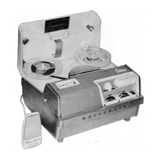
Wollensak Model T-1500 Tape Recorder Service Manual
operate on different supply voltages. The TS-1520 model has an autotransformer which
allows it to operate on 220VAC, 60 Hz as well as 120VAC. The T-1700 model has a
vibrator inverter which allows it operate off of 12.6 VDC as well as 120 VAC.
The tape record is a complete self-contained recording and playback unit, with a self-
contained speaker. The audio output is also made available at the Preamp. Jack,
allowing it to be fed into an existing home music system, or an external speaker may be
connected to the External Speaker Jack.
Versions of the T-1500
I have found there seems to be an ―early‖ and a ―late‖ version of the T-1500 chassis,
which differ slightly in their electronics. The ―early‖ chassis was made between
approximately 1958 and 1961, and the ―later‖ from 1962 onward. The date of
manufacture is stamped on the underside of the electronics chassis.
Although the main text of this manual refers to the later chassis, notes for the 1958
version may be found in the Appendix on page 32. In the text, sections that differ for
the two versions I mark with a ―§‖, so be sure to check the Appendix for them if you have
the 1958 chassis!
By Matthew S. Taylor. Last modified 5
January 2010.
Certain parts taken from:
Howard W. Sams & Co., Inc.
―Wollensak Models T-1500, T-1515-4,
T-1700, TS-1520.‖ Photofact® Set
564, Folder 15. Indianapolis 6,
Indiana: Jan. 1962.
---. ―Wollensak Model T-1500.‖
Photofact® Set 400, Folder 13.
Indianapolis, Indiana: May 1958.
Introduction
This manual is for the Wollensak T-
1500 tape recorder, which is designed
for operation on 120 VAC, 60Hz.
Models TS-1520 and T-1700 are
similar, differing only in the ability to
[1]
Advertisement
Table of Contents
Troubleshooting

Subscribe to Our Youtube Channel
Summary of Contents for Wollensak T-1500
- Page 1 External Speaker Jack. Versions of the T-1500 I have found there seems to be an ―early‖ and a ―late‖ version of the T-1500 chassis, which differ slightly in their electronics. The ―early‖ chassis was made between approximately 1958 and 1961, and the ―later‖ from 1962 onward. The date of manufacture is stamped on the underside of the electronics chassis.
- Page 2 Table of Contents Wollensak Model T-1500 Tape Recorder Service Manual ..........1 Introduction ........................1 Versions of the T-1500 ......................1 Specifications ........................6 Frequency Response ......................6 Wow & Flutter ........................6 Signal-to-Noise Ratio ...................... 6 Tape Speeds ........................6 Tape Required........................
-
Page 3: Table Of Contents
Operating Instructions ......................9 Preparation ........................9 Recording with a Microphone ..................9 Monitoring ........................9 Recording from an External Source ................10 Tape Erasure ........................10 Playback ......................... 10 Playback with External Amplifier ................10 Splicing & Editing ......................10 Use as a Public Address System .................. - Page 4 Insufficient Tape Take-up ..................... 22 Tape Squeal or Squeak ....................22 Troubleshooting Electrical Problems ................22 Weak Playback Volume or No High Frequencies ............22 Recorder Dead, Pilot Light Off ..................23 No Playback or Record ....................23 Plays, But Does Not Record Or Records But Does Not Playback ......... 23 Weak or Distorted Record, Playback of Prerecorded Tape Normal ......
-
Page 6: Specifications
A 7-inch reel of 1-mil tape recorded on both tracks at 3¾ ips will play for 3 hours; other tape lengths, thicknesses, and speeds are proportional. Power Requirements Model T-1500: 120 VAC, 60Hz. Model T-1520: 120 VAC or 220 VAC, 60 Hz. -
Page 7: Function Of Controls, Indicators, And Switches
Function of Controls, Indicators, and Switches Power Switch Rotating the tone control a few degrees clockwise turns the tape recorder on, applying power to both the amplifier and transport motor. Thus the motor is ready to transport the tape immediately whenever the Play or Record keys are pressed or the High Speed Lever actuated. -
Page 8: Instant Stop & Record Lock Lever
in any function (Play, Record, or Stop) and the play or record keys will be automatically released. When the lever is returned to neutral, the recorder is left in the ―Stop‖ mode. Instant Stop & Record Lock Lever The record lock lever is provided as a safety feature to prevent accidental erasure of prerecorded tapes. -
Page 9: Operating Instructions
plug lengths for each application. A short (1-inch) plug is used with the microphone and a longer (1 -inch) plug is used for external audio sources (televisions, radios, &c.). External Speaker Jack An external speaker can be connected to the tape recorder through this jack. The impedance of the speaker should be 6-8Ω. -
Page 10: Recording From An External Source
Playback with External Amplifier 1. Connect the external amplifier to the preamp output jack on the back of the recorder using a shielded cable such as Wollensak A196-13 Hi-Fi cable. 2. Set the recorder’s tone control to ―Hi-Fi.‖ 3. Adjust the recorder’s volume until the ―Normal‖ side of the level indicator flashes. -
Page 11: Use As A Public Address System
sections of tape can be spliced together and reused. Tape should be cut on a diagonal and the ends joined together with splicing tape on the glossy side. Any excess width should be trimmed. Program material can be edited very precisely in the following manner: 1. - Page 12 Figure 2: Top Plate Mechanism Figure 3: Transport Mechanism with Top Mechanism Plate Removed [12]...
- Page 13 Figure 4: Exploded View of Transport Mechanism [13]...
- Page 14 Figure 5: Exploded View of Top Mechanism Plate [14]...
-
Page 15: Disassembly Instructions
Disassembly Instructions To Remove Mechanism from Case 1. Remove top panel. a) Remove five (5) painted screws holding top panel (three screws between reel spindles and one on each forward corner). b) Remove two chrome-plated screws on top of perforated grill directly in front of head cover. -
Page 16: Replacing Sound Head
Replacing Sound Head 1. Remove head retainer spring (137). 2. Lift head and brass alignment plate from head shield cup. 3. Unplug head cable plug. 4. Pry head from brass alignment plate, noting position of location pins. 5. Place the new head over the pins in the aligning plate in the proper location and press into place. -
Page 17: Function Switch Explanation
The wafers can hold 36 stationary contacts in total, but only 31 of these are used on the T-1500, TS-1520, and T-1700 models. Being as both the strips and the contacts are placed at several different ―levels‖ along each wafer, it is difficult to see which contacts are shorted together in each of the three positions. -
Page 18: Electrical Adjustments
If an alignment tape is not available, play a previously-recorded tape and adjust alignment screw (140) for maximum treble response. Azimuth is the only head adjustment needed on Models T-1500, TS-1520, and T-1700. I do not know where such an alignment tape could be found now—MST. -
Page 19: High Frequency Equalization Adjustment
High Frequency Equalization Adjustment § An adjustment is provided in the cathode circuit of V (12AT7) to compensate for high frequency losses which accompany long-term head wear. This equalization has more effect upon the playback than it has upon the recording process; therefore, the adjustment is made for best results during playback. -
Page 20: Cleaning
8. With a plastic (not metal) flat-bladed adjustment tool, adjust bias/erase oscillator coil T for a voltage of 50 VAC. Cleaning The majority of defects, other than wear or breakage, can be traced to dirty surfaces. The play-record and erase heads, capstan, and pressure roller are subject to an accumulation to tape coating residue, which is worn off the tape as it passes these parts. -
Page 21: Take-Up Reel Does Not Turn Although Tape Feeds Past The Capstan
Grease or oil on high (120) or low speed (58) Wipe lubricant off tires. idler tires. Sticking idler slide (59 or 119) Take-up Reel Does Not Turn Although Tape Feeds Past the Capstan Take-up belt (45) broken or off pulley (43). Replace belt or place it back on pulley. -
Page 22: Bottom Motor Shaft Pin Rubs Bottom Ventilating Grill
Supply reel is free to rotate and is not scraping against the top plate. Brakes are completely released. Pressure roller (103) is making good contact with capstan. Pressure roller tension spring (89) should not be too weak or too strong. ... -
Page 23: Recorder Dead, Pilot Light Off
5. Check pressure pads for weak or improper contact. 6. Wrong type or tape or wind. Dull side of tape should be wound ―in‖ (―A‖ wind). 7. Check head azimuth adjustment. 8. Check head for wear. If head is worn, make compensating adjustment (see ―High Frequency Equalization Adjustment‖... -
Page 24: Record Level Indicator Inoperative Or Operation Defective
3. Check microphone or other input source for quality of signal. 4. Check plugs; microphone plug should be a two-circuit plug with shielded wire connected to tip and shield connected to body. Shaft of plug should be approximately 1-in long. High level sources require a two-circuit plug approximately 1 inches long. -
Page 25: Excessive Tape Hiss
Excessive Tape Hiss 1. Check for sufficient recording level by comparing to a prerecorded tape. 2. Tape may be worn, try a new tape of good quality. 3. Check V and associated voltages. 4. Check bias-erase oscillator coil T and associated components. 5. -
Page 26: Resistors
47 nF 250VAC X-Y Metalized Film C24, C27 33 µF 350V Electrolytic 22 nF 250V 3.3 nF 100V Part of Thick-film Printed 100 pF 500V Circuit K 470 pF 1 kV 47 µF 6.3V Electrolytic 100 pF N150 Ceramic 100 µF Electrolytic C38, C41 2 nF ±10%... -
Page 27: Inductors & Transformers
Sec. 2 Impedance: 8Ω Driver Transformer Turns Ratio: 6/5 to each secondary Bias Oscillator Coil Speaker SPK1 5¼-in. PM 8Ω Loudspeaker Rectifiers Part # Original Wollensak # Replacements D1, D2 A123-5 1N1763 or 1N4004 A123-4 1N4007 Fuse 1¼-ampere 125VAC time-delay fuse [27]... -
Page 28: Switches
Switches § Part # Description S1-S6, S9-S13, S15, S16 Part of Function Slide Switch Power switch on tone control, SPST Equalization Switch, SPDT Mic-Rec/Monitor-P.A. Switch; SPDT Motors Drive Motor Single-phase hysteresis induction motor Mechanical Parts List Reference # Quantity Description #6-32 ×... - Page 29 Rewind Spring Counter Worm Shaft & Bracket Assembly Counter Assembly #8-32 × 5/32 in. Pan Head Screws Counter Worm Gear Washer Grip Ring, 3/16 in. Shaft Washer Clutch Plate & Felt Assembly Take-up Clutch Felt Clutch Plate Spring Take-up Pulley Assembly ―E‖...
- Page 30 Motor and Plug Assembly, 115VAC, 60 Hz ―E‖ Ring, ¼ in. Shaft Flat Steel Washer Motor Fan Washer Slow Speed Switch Cam ―E‖ Ring, 3/16 in. Shaft Cam Actuating Stud Lever Assembly ―E‖ Ring Bottom Mechanism Plate Assembly #8-32 × ¼ Pan Head Screws Top Mechanism Plate Assembly ―E‖...
- Page 31 Idler Assembly (WALSCO Part #41-040) Spring Retainer Idler Drive Spring 7 ½ ips Speed Change Arm ―E‖ Ring, 3/16 in. Shaft ―E‖ Ring, 3/16 in. Shaft Two Speed Knob Assembly Detent Spring Steel Ball Cotter Pin 1/16 in. × ⅜ in. Roll Pin Two Speed Arm Shaft High-speed Slide &...
-
Page 32: Appendix: Early Version Procedures & Components
Appendix: Early Version Procedures & Components High Frequency Equalization Adjustment (p. 19) In step 4, you were instructed to adjust the peaking coil for 6 dB (twice the voltage) more output at 10 kHz than at 15 kHz. Bias Current Adjustment (p. 19) Bias is measured by placing a 100 Ω... -
Page 33: Switches
Output Transformer Primary Impedance: 8.8 kΩ CT Sec. 1 Impedance: 130Ω CT Sec. 2 Impedance: 8Ω Driver Transformer Primary Impedance: 25 kΩ Sec. 1 & 2 Impedance: 13 kΩ Bias Oscillator Coil Different winding inductance. Switches (p. 28) Part # Description S1-S6, S9-S11, S13-S15 Part of Function Slide Switch...
Need help?
Do you have a question about the T-1500 and is the answer not in the manual?
Questions and answers