Advertisement
Quick Links
SUMMARY
K EY
P OINTS
O F
A SSEMBLY
!
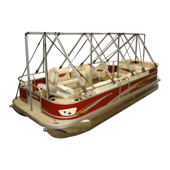
NAVIGLOO
P ONTOON
B OAT
2 3-‐24
f t
LES
1
78''
THE
5
V ERTICAL
S UPPORT
P OSTS
LES
5
P OTEAUX
D E
S OUTIEN
V ERTICAUX
Metal
p ins
( K)
m ust
O NLY
b e
i nstalled
o n
t he
5
v ertical
s upport
p osts.
Les
g oupilles
d e
m étal
( K)
d oivent
ê tre
p osées
U NIQUEMENT
s ur
l es
5
p oteaux
d e
s outien
v erticaux.
Carabiners
( G1)
o f
t he
s traps
m ust
O NLY
b e
i nstalled
o n
t he
C -‐ C LIPS
( C)
s ecuring
t he
5
v ertical
s upport
posts.
Les
m ousquetons
( G1)
d es
s angles
d oivent
ê tres
i nstallés
U NIQUEMENT
s ur
l es
C -‐ C LIPS
( C)
d es
5
p oteaux
d e
soutien
v erticaux.
It
i s
i mportant
t hat
t he
h orizontal
b eam
b e
l evelled
a s
m uch
a s
p ossible.
A djust
t he
v ertical
p osts
accordingly.
Il
e st
i mportant
q ue
l a
p outre
h orizontale
s oit,
l e
p lus
p ossible,
d e
n iveau.
A juster
l es
p oteaux
v erticaux
e n
conséquence.
The
v ertical
s upport
p osts
r equire
a
h eight
o f
7 8
i nches.
I t
i s
r ecommended
t hat
t his
h eight
b e
m aintained
to
e nsure
g reater
f rame
s tability
a nd
a chieve
t he
p roper
p itch
t o
a llow
s now
t o
s lide
o ff.
7 8''
Les
p oteaux
d e
s outien
v erticaux
d oivent
a voir
u ne
h auteur
d e
7 8
p ouces.
I l
e st
r ecommandé
d e
m aintenir
cette
h auteur
a fin
d 'assurer
u n
m aximum
d e
r obustesse
à
l 'armature
e t
d 'obtenir
l a
m eilleure
p ente
possible
p our
q ue
l a
n eige
s 'écoule.
The
d istance
b etween
t he
5
v ertical
s upport
p osts
m ust
b e
m ore
o r
l ess
e qual
i n
o rder
t o
h ave
g reater
stability
( they
a re
t he
5
p illars
o f
t he
f rame).
L'espace
e ntre
l es
5
p oteaux
d e
s outien
v erticaux
d oit
ê tre
l e
p lus
é quilibré
p ossible
p our
a ssurer
u ne
b onne
stabilité
( puisqu'il
s 'agit
d es
5
p iliers
d e
l 'armature).
[10''-‐
2 4'']
±
90°
5
THE
V ERTICAL
S UPPORT
P OSTS:
T HE
P ILLARS
O F
T HE
F RAME
5
P OTEAUX
D E
S OUTIEN
V ERTICAUX:
L ES
P ILIERS
D E
L 'ARMATURE
2
K
K
THE
2
V ERTICAL
C ONNECTORS
LES
2
E MBRANCHEMENTS
V ERTICAUX
Leave
a
1 0
t o
2 4
i nch
m aximum
o verhang
p ast
t he
2
v ertical
s upport
p osts
with
b ase
( front
&
b ack)
s o
t hat
t he
h orizontal
b eam
r emains
s ecure.
Les
2
e mbranchements
v erticaux
s ans
b ase
( avant
&
a rrière)
d oivent
ê tre
[10''-‐
2 4'']
installés
à
c hacune
d es
e xtrémités
d e
l 'armature
à
u ne
d istance
d e
1 0
à
2 4
pouces
m aximum
d es
p oteaux
d e
s outien
a vec
b ase
( avant
e t
a rrière)
a fin
d'assurer
l a
s tabilité
d e
l a
p outre
h orizontale.
Make
s ure
t hat
e ach
e xtremity
( front
a nd
b ack)
e nds
a t
a
90°
±
Les
2
e mbranchements
v erticaux
s ans
b ase
( avant
e t
a rrière)
d oivent
f ormer
un
a ngle
d e
©
N AVIGLOO
P ONTOON
B OAT
-
P ONTON
2
RÉSUMÉ
3
K
90°
a vec
l a
p outre
h orizontale.
±
3-24
S UMMARY:
K ey
P oints
o f
A ssembly
I nstructions
/
R ÉSUMÉ:
P oints
c lés
d e
l 'assemblage
P OINTS
C LÉS
D E
L 'ASSEMBLAGE
!
NAVIGLOO
P ONTON
2 3-‐24
p i
4
5
K
K
:
f ront
&
b ack
W ITHOUT
B ASE
:
a vant
&
a rrière
S ANS
B ASE
90°
a ngle.
±
1/3
Pages
6 ,
1 2
Pages
7 ,
1 3
Pages
6 ,
1 2
Pages
6
Pages
1 2
Page
9
Page
1 0
Advertisement

Summary of Contents for Navigloo 3500
- Page 1 P OINTS C LÉS D E L ’ASSEMBLAGE NAVIGLOO P ONTOON B OAT 2 3-‐24 f t NAVIGLOO P ONTON 2 3-‐24 p i ...
- Page 2 P OINTS C LÉS D E L ’ASSEMBLAGE NAVIGLOO P ONTOON B OAT 2 3-‐24 f t NAVIGLOO P ONTON 2 3-‐24 p i ...
- Page 3 P OINTS C LÉS D E L ’ASSEMBLAGE NAVIGLOO P ONTOON B OAT 2 3-‐24 f t NAVIGLOO P ONTON 2 3-‐24 p i ...

