Advertisement
Quick Links
Installation Guide for Unovent
system, including the Unobrain
and-forget, fully automated controller.
install-and-forget Unobrain
the outside source air temperature and/or humidity makes this
resource unsuitable for short periods.
Please read this entire document thoroughly before
commencing the installation.
For the cable supplied, it is essential that the cable core
marked red or white is always fitted to the plug and
socket connectors marked with a red stripe.
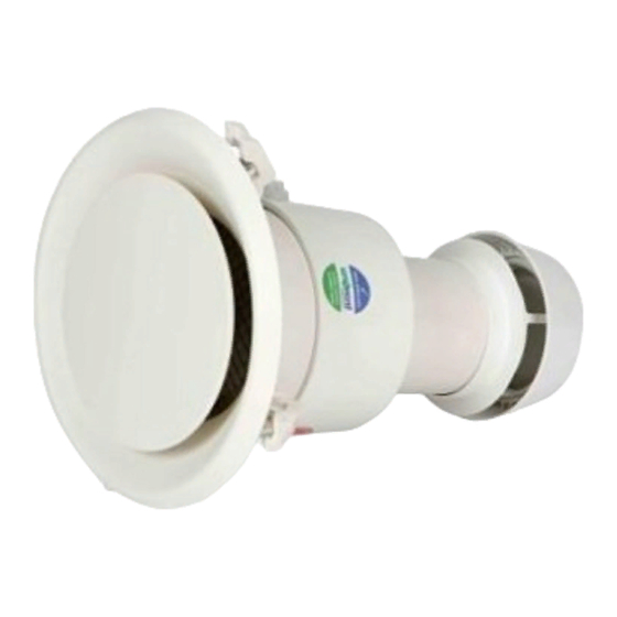
All product and component photos within this guide are for
illustrative purposes only and colours, shapes and
components used in the supplied product may change at any
time but retain the same or improved functionality of the items
illustrated.
These guidelines have the
purpose of helping the
experienced and inexperienced
manage the task of installing the
Unovent
h-line
®
rooms with no roof cavity above
including the fully automatic,
for managing the system when
®
1
Dwelling
Moisture
Management
h-line
™
®
install-
®
system for
™
Version H180917
Advertisement

Summary of Contents for Unovent h-line
- Page 1 Dwelling Moisture Management Installation Guide for Unovent h-line ™ ® system, including the Unobrain install- ® and-forget, fully automated controller. These guidelines have the purpose of helping the experienced and inexperienced manage the task of installing the Unovent h-line system for ®...
- Page 2 (Unovent Limited does not take any responsibility for the finished water tightness or otherwise for the installation.) 2. Decide where you plan to install the outer wall mounted Unovent room outlets in each room selected.
- Page 3 In the case of a brick veneer external cladding, the same approach could be taken with an extra-long masonry drill to create a hole through the brick cladding which will be the centre point of the Unovent room ®...
- Page 4 This means that the hole in the outer brick cladding will need to allow for a diameter of 110 mm (55 mm radius) to take the inlet tube section of the Unovent room outlet. ® 9. The Unovent...
- Page 5 (this is the 12 volt positive connection). The other unmarked cable has its cable ends connected to the unmarked socket. Where there are two cable pairs hanging out of the Unovent ® room outlet hole, both pairs are connected into the socket using these colour matches.
- Page 6 240 volt switched outlet, turn the power on then fit the Unovent room outlets into ® position one by one. 15. Before placing each Unovent room outlet into its final ® position, connect the cable connected socket onto the...
- Page 7 ® fully ensure that there will be no water ingress into the external wall structure. The external cowl can then be fixed to the inlet tube section of the Unovent room outlet ®...
- Page 8 PVC glue or small stainless screws, the latter making it easier to remove at any time in the future. 18. Steps 15. to 17. are repeated for all Unovent room ® outlets. 19. The supplied Unobrain fully ® automated install-and-forget...
- Page 9 Unovent room ®...
- Page 10 23. In the warm summer months, not known for condensation issues but a time when moisture is being introduced into the living spaces by the people living in the house, it is advisable to leave the Unovent system switched on 24/7 ®...
- Page 11 10. The Unovent® product design is covered by New Zealand Patent Application 629739, Australian Patent Application 2015201820 with other International Rights Reserved for this unique product design and options for dwelling ventilation moisture reduction.
- Page 12 Unovent typical wiring (red or white marked cables are ® always connected to red marked plugs and sockets)
Need help?
Do you have a question about the h-line and is the answer not in the manual?
Questions and answers