Advertisement
Quick Links
4. OPC Signal Output Specifications
4-1.OPC output signals
For the OPC signal output specifications, refer to Table 1. For the timing chart of the OPC signal output.
*Do not use the device with any current exceeding the ratings of +30V and 10mA for each OPC signal output pin.
Table 1. OPC Signal Output Specifications
Signal Name CN3 Connector Signal Output PIN
FOR signal
PIN4
T-UP signal
PIN2
REV signal
PIN6
4-2. D_ACT input signals
*Use devices rated at +50V, 20mA or more to open/close the D_ACT terminal and GND terminal.
Figure 3 Timing Chart of the OPC Signal Output
CN3 Connector Signal
Signal Name
Input PIN
ON (short-circuit between PIN3-GND)
D_ACT
PIN3
OFF (open-circuit between PIN3-GND)
4-3. OPC output signals and D_ACT input signals Timing Chart
OPC output signals and D_ACT input signals Timing Chart
1. Positive rotation movement of the driver controlled by external
devices and the clutch movement.
① Pull and tie the screwdriver's
Switch Lever with a plastic belt.
② D_ACT input signal turns ON.
→ FOR output signal turns ON. (The
(D_ACT terminal – GND terminal
driver rotates clockwise.)
shorts out)
③ The screwdriver clutch activates.
→ T-UP (finish) output signal turns
• T-UP (finish) output signal turns
ON, the signal lasts for 50ms. (The
ON.
screwdriver stops)
* FOR signal does not turn OFF automatically in conjunction with T-UP (finish)
signal.
④ D_ACT input signal turns OFF (D_
ACT terminal – GND terminal opens)
2. Reverse rotation movement of the driver controlled by external devices.
① Pull and tie the screwdriver's
→ REV signal output 0V.
Switch Lever with a plastic belt.
(Screwdriver reverse rotation)
• Because there is no torque up during reverse rotation, the T-UP signal is
turned off and the output becomes.
② D_ACT input signal turns ON.
→ REV output signal turns ON. (The
(D_ACT terminal – GND terminal
driver rotates counterclockwise.)
shorts out)
• T-UP (finish) signal is OFF as there is no clutch activation during reverse rotation.
③ D_ACT input signal turns OFF.
→ REV output signal turns OFF.
(D_ACT terminal – GND terminal opens)
5. Accessories
(1) Instruction Manual (1 copy)
(4) 5P screwdriver cord [for power supply connection] <1.5m> ( 1pc)
Output Conditions
Output Method
Screwdriver forward rotation
Open collector output
Screwdriver torque up
(Low active)
Screwdriver reverse rotation
Input signals
Control of driver
Driver starts up
Driver shuts down
Lever Start
Lever Start
(2) Brackets (2 pcs)
(3) OPC signal plug (1 pc)
HIOS Inc.
1-16-5 Akiyama, Matsudo City, Chiba Pref., Japan
TEL: +81 (JAPAN) 47-392-2001
FAX: +81 (JAPAN) 47-392-7773
1. Overview of the Device
By connecting this interface box to a set of the BL-OPC or BLG-OPC and its power supply, these drivers
can start up / shut down by inputting D_ACT signals into the CN3 connector with external devices.
In addition, to facilitate the use of the OPC signal by external devices, the device converts the +30V,
which is the rated voltage of BL series screwdrivers, to +24V by using a regulator and outputs it to the
CN3 connector, the same output location as the OPC signal.
2. Precautions about Usage <<Please read the instructions below before use>>
Be aware that using the device without following these instructions may result in a malfunction of or breakdown with
the device and its power supply and screwdriver.
(1) Correctly connect the BL-OPC or BLG-OPC screwdriver and the power supply for BLor BLG to the specified
connectors of the device.Wrong connection may result in malfunction or breakdown.
(2) Do not directly connect the +24V pin of the CN3 connector or the external +24V power supply to the BL-OPC or
BLG-OPC signal pins of the CN3 connector.
(3) Set the speed selector switch of the power supply for BL or BLG to HI.If it is used at LOW, the output voltage of
the +24V pin of the CN3 connector decreases accordingly, resulting in a malfunction.
(4) Do not overload to the BL-OPC screwdriver. If the +30V voltage of the power supply for BL decreases to +25V
or lower due to overloading, the voltage at the +24V pin of the CN3 connector decreases accordingly, resulting
in a malfunction.
(5) If an external device requires a constant voltage of +24V without being affected by overloading, prepare a
separate external power supply for the external output circuit.
(6) Do not use the +24V output of the CN3 connector for any purpose other than for the OPC signal. Otherwise,
overcurrent will flow through the internal circuit of the BL-OPC screwdriver, resulting in a breakdown. Other
unspecified usage will affect the screwdriver's tightening performance or result in a malfunction or breakdown.
(7) Avoid any usage in which the ratings of +30V and 10mA will be exceeded for each OPC signal pin of the CN3
(one-shot output)
connector. Overcurrent will result in a malfunction of or breakdown with the device and the screwdriver.
(8) Use devices rated at +50V, 20mA or more to open/close the D_ACT terminal and GND terminal.
(9) Do not directly connect external devices in which noise may occur, such as relays, motors, buzzers, and lamps,
to the OPC signal pins of the CN3 connector. Drive noise or overcurrent from external devices will result in a
malfunction of or breakdown with the device and the BL-OPC screwdriver.If external devices in which noise may
occur need to be connected, mount noise suppression components such as photo couplers and diodes with
reference to Examples 5 and 6 in Figure 2, and carefully confirm the effectiveness before use.
3. How to Use the Device
(1) Connect the device with the BL-OPC or BLG-OPC screwdriver and the power supply for BL or BLG using a scre-
driver cord, as shown in Figure 1.
(2) Connect external devices to the CN3 connector of the device.
(3) Fix the Switch Lever of the driver to keep it on.
(4) Turn on the power of the power supply for the screwdriver.
(5) The OPC signal is output from the CN3 connector according to the operation of the screwdriver.
*For OPC signal output specifications and timing, refer to 4. OPC Signal Output Specifications.
(6) The driver starts up by connecting the D_ACT terminal and GND terminal of the CN3 connector with external
devices.
(7) The driver shuts down by disconnecting the D_ACT terminal and GND terminal of the CN3 connector.
BLOP-OST2 Relay Box
Instruction Manual
As of January 2017 Registration Number: No.ET-A060 17A
Advertisement

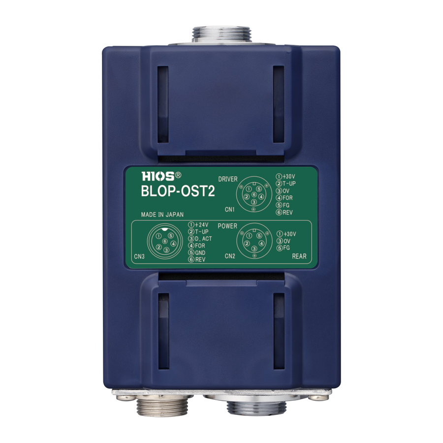
Summary of Contents for HIOS BLOP-OST2
- Page 1 For the OPC signal output specifications, refer to Table 1. For the timing chart of the OPC signal output. BLOP-OST2 Relay Box *Do not use the device with any current exceeding the ratings of +30V and 10mA for each OPC signal output pin.
- Page 2 Figure 1 Connection drawing OPC Screwdriver Power supply for BL BLOP-OST2 DRIVER 6P Metal POWER IN 5P Metal T-30BL (Discontinued model)* Connector Front View Connector Front View T-45BL BL-OPC Screwdriver 1:+30V 1:+30V T-70BL Power Output BLG-OPC Screwdriver +30V +30V 2:T-UP...