Table of Contents
Advertisement
Advertisement
Table of Contents

Summary of Contents for Riken Keiki FI-21
- Page 1 FI-21 Operator’s Manual Optical Gas Indicator...
- Page 2 Warning Read and understand this instruction manual before operating instrument. Improper use of the gas monitor could result in bodily harm or death. Periodic calibration and maintenance of the gas monitor is essential for proper operation and correct readings. Please calibrate and maintain this instrument regularly! Frequency of calibration depends upon the type of use you have and the sensor types.
-
Page 3: Warranty
Warranty Control Equipment Pty Ltd warrants gas alarm equipment sold by us to be free from defects in materials, workmanship, and performance for a period of one year from date of shipment from Control Equipment Pty Ltd. Any parts found defective within that period will be repaired or replaced, at our option, free of charge. -
Page 4: Table Of Contents
Contents WARRANTY .................................. 3 PARTS AND FUNCTION ............................ 7 MEASURING MODE (POWER KEY) ........................9 Basic Display for Measuring Mode and Explanation ..................9 Procedures from Power ON to Measurement ....................10 Saving Data ..............................12 Initial Display (Self-diagnostic Display) ......................12 AIR CAL. - Page 5 10.0 MEASURING PRINCIPLE ..........................23 11.0 TYPE-01 SPECIFICATIONS .......................... 24 12.0 TYPE-02 SPECIFICATIONS .......................... 25 13.0 TYPE-03 SPECIFICATIONS .......................... 26 14.0 TYPE-04 SPECIFICATIONS .......................... 27 15.0 TYPE-05 SPECIFICATIONS .......................... 28...
- Page 6 NOTE: Manufacturers advisory comment As the kinds of measurable gas and range are different depending on the type of FI-21, refer to the attached measuring gas specification. For standard models, refer to the attached “each TYPE measuring gas specification”.
-
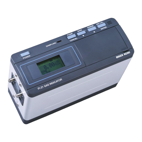
Page 7: Parts And Function
1.0 Parts and Function POWER key: Press this key to turn the power on until buzzer beeping. Keep pressing the key approx. 3 seconds to turn the power off. When pressing the POWER key and (7) ENTER key, you can enter the “SETTING MODE”. LCD Display: Concentration is displayed. - Page 8 Inlet for measuring gas. A specific absorption tube must be connected to the inlet. Otherwise, the reading might go wrong. Outlet connected to the reference gas chamber. The exhaust from the outlet has to be emitted into the fresh air at atmospheric pressure. Outlet for measuring gas sucked from the GAS IN.
-
Page 9: Measuring Mode (Power Key)
2.0 MEASURING MODE (POWER KEY) Basic Display for Measuring Mode and Explanation Display Contents Status Gas Name and Usual measuring mode. Base Gas CAUTION Zero drifting might be occurring. Let the monitor sample the fresh air and CHECK AIR CAL. perform AIR CAL. -
Page 10: Procedures From Power On To Measurement
Procedures from Power ON to Measurement Power turns on by pressing the POWER key until buzzer beeps. And, the initial display (self-diagnostic display) shows up. It then turns to a display to confirm the setting. After showing the confirmation display for 2 seconds, it goes to the basic display of measuring mode. - Page 11 Read the indication after the gas flow stops. * NOTE: FI-21 measures the gas best when both Gas Chamber and Reference Chamber are at 101.3kPa. If precise measurement is required, perform the pressure correction by the...
-
Page 12: Saving Data
2.3 Saving Data Once the SAVE key is pressed, the buzzer beeps and the display shown on the right comes up. The time/ data and the measurement result are saved chronologically from No.001 to No.100. The saved data can be seen at “VIEW SAVED DATA” in the SETTING MODE. -
Page 13: Affection On Measurement From Pressure
Read the indication after the gas flow stops. CAUTION: When concentration change occurs suddenly on the FI-21, correct reading cannot indicate. Absorption tube is also for stabilizing the temperature of the sampling gas. Therefore, equip an absorption tube on the GAS IN whenever the measurement is performed. - Page 14 An example of measurement when the measured gas is not released in to the air: Connect a gas sampling bag to the GAS OUT, not to emit the exhaust into the air. And also, expose the REF. OUT to the fresh air.
-
Page 15: Setting Mode (Enter + Power)
SETTING OK?” appears. Press [ENTER] key again if it is okay. If you want to change the setting, press the [CANCEL] key. The kinds of selectable measuring gas and range are different depending on the type of FI-21. For the information, refer... -
Page 16: Adjusting The Time (Set Date / Time)
3.2 Adjusting the Time (SET DATE / TIME) Initial position of the cursor is on YEAR. Choose by ▼▲keys and fix the setting by the ENTER key. The cursor then moves to DAY. Set DAY, YEAR, HOUR and MINUTE by the same procedures as MONTH. HOUR is displayed by 24 hour clock. 3.3 Confirming the Saved Data (VIEW SAVED DATA) On the 1st line, the data number is shown. -
Page 17: Maintenance
MAINTENANCE 4.1 Replacing the Batteries WARNING: All the C size Alkaline batteries used in the instrument should be same kind. Replace the 4 of the batteries at the same time. a) Confirm that the power is off. b) Take out the instrument from the carrying case. Take off the battery cover under the bottom by turning the screw with a coin. -
Page 18: Disposing The Instrument
DISPOSING THE INSTRUMENT This instrument does not apply any harmful material as component parts. When the instrument is disposed, take an appropriate method based on the local regulation. TROUBLE SHOOTING Trouble shootings mentioned below do not cover all the problems. The ones considered frequently occur are simply indicated to help your research for cause and solution. -
Page 19: Caution Of Usage
CAUTION OF USAGE DANGER: The following caution items must be followed to maintain the performance/ safety of the instrument. Specification of this instrument is based on a non-explosion structure. Do not use it in a place specified as a hazardous area. -
Page 20: Defenition Of Terms
DEFENITION OF TERMS Terms Description vol% The rate of substance occupying in some volume. The unit is indicated by percentage. The rate of substance occupying in some volume. The unit is indicated by ppm “parts per million”. %LEL This is the unit when defining the Lower Explosive Limit of a combustible gas as 100%. -
Page 21: Specifications
SPECIFICATIONS 9.1 Specifications Detection principle Optical Interferometric method Display Digital display (Measuring gas, base gas, gas concentration, time, etc) Structure Non-explosion proof Measuring method Batch measurement Gas sampling method Suction by internal pump (Pump stops operation while reading) Indication accuracy Within + 3% of the indication value + 1 digit Outputs Data logger, 0-1VDC... -
Page 22: Standard Accessories
TYPE APPLICATION NAME OF GAS MEASURING GAS RANGE Type-01 Vol% solvent Toluene in air in air 0 – 2%vol gases applications Methyl ethyl ketone in air MEK in air 0 – 5%vol Ethyl acetate in air EtAc in air 0 – 5%vol Xylene in air in air 0 –... -
Page 23: Measuring Principle
(concentration) can be determined by measuring the reflection ration. The optic interferometer applied in the FI-21 displays “Interference Stripes” on the CCD. The Interference stripes move proportional to reflection ratio. The amount of the movement is measured by solution of the interference stripes on CCD with Fourier analysis. -
Page 24: Type-01 Specifications
11.0 TYPE-01 SPECIFICATIONS FOR SOLVENTGASES (vol%) Selectable measuring gas and range Measuring gas Measuring range AIR CAL value Drift amount Spec. No. Display indication (Minimum digit Toluene in AIR 0.000 vol% 0.017 vol% SPE-1428 0~2 vol% C7H8 in AIR (0.002 Methyl ethyl ketone in AIR 0.000 vol% 0.027 vol%... -
Page 25: Type-02 Specifications
12.0 TYPE-02 SPECIFICATIONS FOR SOLVENT GASES (%LEL) Selectable measuring gas and range Measuring gas Measuring range AIR CAL value Drift amount Spec. No. Display indication (Minimum digit Toluene in AIR 0.0 %LEL 1.4%LEL SPE-1434 0~100%LEL C7H8 in AIR (0.2) Methyl ethyl ketone in AIR 0.0 %LEL 1.5%LEL SPE-1435... -
Page 26: Type-03 Specifications
13.0 TYPE-03 SPECIFICATIONS FOR FUMIGATION GASES Selectable measuring gas and range Measuring gas Measuring range AIR CAL value Drift amount Spec. No. Display indication (Minimum digit Methyl bromide in AIR 0.0 mg/l 1.7 mg/l SPE-1405 0~200 mg/l (CH3Br in AIR) (0.2) Phosphine in AIR 0.0 mg/l... -
Page 27: Type-04 Specifications
14.0 TYPE-04 SPECIFICATIONS FOR GAS PURITY Selectable measuring gas and range Measuring gas Measuring range AIR CAL value Drift amount Spec. No. Display indication (Minimum digit Helium in AIR 0.00 vol% 0.46 vol% SPE-1411 0~100 vol% (He in AIR) (0.05) Neon in AIR 0.0 vol% 0.5 vol%... -
Page 28: Type-05 Specifications
15.0 TYPE-05 SPECIFICATIONS FOR ANAESTHETIC GAS ES Selectable measuring gas and range Measuring gas Measuring range AIR CAL value Drift amount Spec. No. Display indication (Minimum digit Halothane in O2 1.57 vol% 0.09 vol% SPE-1401 0∼6 vol% ( (HALOTHANE in O2) 0.01) Iso urane in O2 1.65 vol%...
Need help?
Do you have a question about the FI-21 and is the answer not in the manual?
Questions and answers