Table of Contents
Advertisement
Quick Links
Bardac
drives
P2 Series
AC Vector Drive
For Precision Industrial Motor Speed & Torque Control
0.75 - 160kW / 1HP - 250HP
200 - 480V 1 / 3 Phase Input
Quick Start Up
General Information
and Ratings
Mechanical Installation
Electrical Installation
Keypad and Display Operation
Parameters
Control Terminal
Parameters
Communications
Technical Data
Troubleshooting
1
2
3
4
5
6
7
Functions
Extended
8
Serial
9
10
11
Advertisement
Chapters
Table of Contents

Summary of Contents for Bardac drives P2 Series
- Page 1 Bardac drives P2 Series AC Vector Drive For Precision Industrial Motor Speed & Torque Control 0.75 - 160kW / 1HP - 250HP 200 - 480V 1 / 3 Phase Input Quick Start Up General Information and Ratings Mechanical Installation Electrical Installation...
-
Page 2: Table Of Contents
4. 1 4. Safe Torque Off ......P2 Series User Guide | Version 3.01... - Page 3 Declaration of Conformity Bardac Corporation hereby states that the P2 Series product range conforms to the relevant safety provisions of the following council directives: 2014/30/EU (EMC) and 2014/35/EU (LVD) Designed and manufacture is in accordance with the following harmonised European standards: EN 61800-5-1: 2007 Adjustable speed electrical power drive systems.
-
Page 4: Electrical Installation
Do not attempt to carry out any repair of the drive. In the case of suspected fault or malfunction, contact your local Bardac Sales Partner for further assistance. Do not operate the drive with any of the enclosure covers removed. P2 Series User Guide | Version 3.01 www.bardac.com... -
Page 5: Parameters
Connect the control cables as required for the 4. 1 0. Control Terminal Connections application. Thoroughly check the installation and wiring. Commission the drive parameters. 5.5. Changing Parameters 6. Parameters www.bardac.com Version 3.01 | P2 Series User Guide | 5... -
Page 6: General Information And Ratings
Three Digit Power Rating 4 : Internal Brake Chopper Input Phases Power Type EMC Filter K : kW Rated 0 : No Internal Filer H : HP Rated F : Internal EMC Filter P2 Series User Guide | Version 3.01 www.bardac.com... -
Page 7: Technical Data
The product rating label provides the following information. Model Code Bardac drives Enclosure Type and IP Rating Firmware Version P2-24010-3HF42 Serial Number Technical Data – Supply Voltage Technical Data – Maximum continuous output current www.bardac.com Version 3.01 | P2 Series User Guide | 7... - Page 8 2. 1 P2-26150-3K042 P2-26020-3H042 3. 1 P2-26220-3K042 P2-26030-3H042 4. 1 P2-26400-3K042 P2-26050-3H042 P2-26550-3K042 P2-26075-3H042 P2-36075-3K042 P2-36100-3H042 P2-361 10-3K042 P2-36150-3H042 P2-36150-3K042 P2-36200-3H042 P2-46185-3K042 18.5 P2-46250-3H042 P2-46220-3K042 P2-46300-3H042 P2-46300-3K042 P2-46400-3H042 P2-56370-3K042 P2-56050-3H042 P2-56450-3K042 P2-56060-3H042 P2 Series User Guide | Version 3.01 www.bardac.com...
-
Page 9: Drive Model Numbers – Ip55
HP Model Number Output Current (A) Frame Size P2-46150-3K04N P2-46200-3H04N P2-46185-3K04N 18.5 P2-46250-3H04N P2-46220-3K04N P2-46300-3H04N P2-46300-3K04N P2-46400-3H04N P2-56370-3K04N P2-56050-3H04N P2-56450-3K04N P2-56060-3H04N P2-66055-3K0#N P2-66075-3H0#N P2-66075-3K0#N P2-66100-3H0#N P2-66090-3K0#N P2-66125-3H0#N P2-661 10-3K0#N 1 10 P2-66150-3H0#N www.bardac.com Version 3.01 | P2 Series User Guide | 9... -
Page 10: Drive Model Numbers – Ip66
2. 1 P2-26150-3K04X P2-26150-3K04Y P2-26020-3H04X P2-26020-3H04Y 3. 1 P2-26220-3K04X P2-26220-3K04Y P2-26030-3H04X P2-26030-3H04Y 4. 1 P2-26400-3K04X P2-26400-3K04Y P2-26050-3H04X P2-26050-3H04Y P2-26550-3K04X P2-26550-3K04Y P2-26075-3H04X P2-26075-3H04Y P2-36075-3K04X P2-36075-3K04Y P2-36100-3H04X P2-36100-3H04Y P2-361 10-3K04X P2-361 10-3K04Y P2-36150-3H04X P2-36150-3H04Y P2 Series User Guide | Version 3.01 www.bardac.com... -
Page 11: Mechanical Installation
100% 1 Hour 2 – 3 Years 30 Minutes 30 Minutes 30 Minutes 100% 30 Minutes More than 3 Years 2 Hours 2 Hours 2 Hours 100% 2 Hours 100% www.bardac.com Version 3.01 | P2 Series User Guide | 11... -
Page 12: Mechanical Dimensions And Weight
*The IP20 Frame Size 4 Chassis can obstruct the rotation (tightening) of a bolt or screw with a hex head, a fixing with a round NOTE head will be most suitable for the mounting of this unit. P2 Series User Guide | Version 3.01 www.bardac.com... - Page 13 Required Torque Control Terminals 0.5 Nm 4.5 lb-in 2 Nm 18 lb-in 5/16 4 Nm 35.5 lb-in Power Terminals 5/16 15 Nm 1 1 lb-ft 15 Nm 1 1 lb-ft www.bardac.com Version 3.01 | P2 Series User Guide | 13...
- Page 14 4.2 0. 1 7 8.5 0.33 7.7 16.8 Mounting Bolts Tightening Torques Frame Size Metric Frame Size Required Torque Control Terminals 0.5 Nm 4.5 lb-in Power Terminals 2 & 3 1 Nm 9 lb-in P2 Series User Guide | Version 3.01 www.bardac.com...
-
Page 15: Guidelines For Enclosure Mounting (Ip20 Units)
Dimension Z assumes that the drives are mounted side-by-side with no clearance. NOTE Typical drive heat losses are <3% of operating load conditions. Above are guidelines only and the operating ambient temperature of the drive MUST be maintained at all times. www.bardac.com Version 3.01 | P2 Series User Guide | 15... -
Page 16: Mounting The Drive – Ip20 Units
Typical drive heat losses are approximately 3% of operating 7.87 0.39 load conditions. NOTE Above are guidelines only and the operating ambient 7.87 0.39 temperature of the drive MUST be maintained at all times. 7.87 0.39 P2 Series User Guide | Version 3.01 www.bardac.com... -
Page 17: Guidelines For Mounting (Ip66 Units)
Typical drive heat losses are approximately 3% of operating load conditions. NOTE Above are guidelines only and the operating ambient temperature of the drive MUST be maintained at all times. www.bardac.com Version 3.01 | P2 Series User Guide | 17... -
Page 18: Removing The Terminal Cover
Terminal Cover Release Screws P2 Series User Guide | Version 3.01 www.bardac.com... -
Page 19: Routine Maintenance
Checks should also be made on all electrical connections, ensuring screw terminals are correctly torqued; and that power cables have no signs of heat damage. www.bardac.com Version 3.01 | P2 Series User Guide | 19... -
Page 20: Electrical Installation
4.3.3. Fuse / Circuit Breaker Selection 4.3.4. Optional Input Choke 4. 1 3. EMC Compliant Installation 4.6. Motor Connection 4.8. Connecting a Brake Resistor 4.5. Operation with DC Power Supply or Common DC Bus P2 Series User Guide | Version 3.01 www.bardac.com... -
Page 21: Protective Earth (Pe) (Ground) Connection
The safety ground terminal provides a grounding point for the motor cable shield. The motor cable shield connected to this terminal (drive end) should also be connected to the motor frame (motor end). Use a shield terminating or EMI clamp to connect the shield to the safety ground terminal. www.bardac.com Version 3.01 | P2 Series User Guide | 21... -
Page 22: Incoming Power Connection
P2 models provide terminals to directly connect to the DC Bus for applications which require this. For further information on using the DC Bus connections, please refer to your Bardac sales Partner. P2 Series User Guide | Version 3.01 www.bardac.com... -
Page 23: Motor Connection
Signal levels of different voltages e.g. 24 Volt DC and 1 10 Volt AC, should not be routed in the same cable. Maximum control terminal tightening torque is 0.5Nm. Control Cable entry conductor size: 0.05 – 2.5mm / 30 – 12 AWG. www.bardac.com Version 3.01 | P2 Series User Guide | 23... -
Page 24: Control Terminal Connections
Relay 1 has both normally open and normally closed contacts available. Relay 2 provides a simple open or closed contact. The relay output function may be configured using parameters P2-15 and P2-18, which are described in section 8. 1 . Parameter Group 2 - Extended Parameters on page 44. P2 Series User Guide | Version 3.01 www.bardac.com... -
Page 25: And Potentiometer Wiring
“External Trip”, e.g. P1-13 = 6. Refer to section 7.2. Digital Input Configuration Parameter P1-13 on page 39 for further details. E nable the Motor PTC Thermistor Input function in parameter P2-33. www.bardac.com Version 3.01 | P2 Series User Guide | 25... -
Page 26: Emc Compliant Installation
For IP55 and IP66 drives, connect the motor cable shield to the gland plate or internal ground clamp. P2 Series User Guide | Version 3.01 www.bardac.com... -
Page 27: Safe Torque Off
The “STO“ function is recognised as a fail-safe method even in the case where the “STO“ signal is absent and a single fault within the drive has occurred, the drive has been proven in respect of this by meeting the following safety standards: www.bardac.com Version 3.01 | P2 Series User Guide | 27... -
Page 28: P2 Series User Guide | Version 3.01
“STO” Fault Codes Fault Code Code Number Description Corrective Action A fault has been detected within either of the Refer to your Bardac Sales “Sto-F” internal channels of the “STO” circuit. Partner P2 Series User Guide | Version 3.01 www.bardac.com... -
Page 29: P2 Series User Guide | Version 3.01
Wires should be protected against short circuits as shown above NOTE The Maximum cable length from Voltage source to the drive terminals should not exceed 25 mtrs. www.bardac.com Version 3.01 | P2 Series User Guide | 29... -
Page 30: P2 Series User Guide | Version 3.01
(Minimum once per Year), furthermore the function should be integrity tested following any safety system modifications or maintenance work. If drive fault messages are observed refer to section 1 1. 1 . Fault Messages on page 74 for further guidance. P2 Series User Guide | Version 3.01 www.bardac.com... -
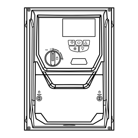
Page 31: Keypad And Display Operation
15kW 400V 3Ph English English Hold down the Start Use the Up and Down Press the Navigate and Up keys for >1s arrows to select a button to select. language. www.bardac.com Version 3.01 | P2 Series User Guide | 31... -
Page 32: Additional Display Messages
8.2.3. Parameter 24 Volt source, with exceeds the motor is missing. time has elapsed. Group 4 – High no mains power rated current entered Performance Motor applied. in Parameter P1-08. Control on page P2 Series User Guide | Version 3.01 www.bardac.com... -
Page 33: Changing Parameters
If P1-13 > 0, switch off digital input 1, then back on again. If P1-12 = 4, reset via the fieldbus interface. If P1-12 = 6, reset via CAN. www.bardac.com Version 3.01 | P2 Series User Guide | 33... -
Page 34: Keypad Short Cuts
Stop and parameter selection keys simultaneously. press will move and down keys. Navigate will return the menu. another digit to the cursor to the right most left. digit. P2 Series User Guide | Version 3.01 www.bardac.com... -
Page 35: Parameters
Acceleration ramp time from 0 to base speed (P-1-09) in seconds. FS2 & FS3 : 5.0 Seconds Default Setting, 0.01 Seconds Resolution, 600.0 Seconds Maximum. FS4 – FS7 : 10.0 Seconds Default Setting, 0. 1 Seconds Resolution, 6000 Seconds Maximum. www.bardac.com Version 3.01 | P2 Series User Guide | 35... - Page 36 Excessive voltage boost levels may result in increased motor current and temperature, and force ventilation of the motor may be required. An automatic setting () is also possible, whereby the drive will automatically adjust this parameter based on the motor parameters measured during an autotune. P2 Series User Guide | Version 3.01 www.bardac.com...
- Page 37 P1-14 = P2-40 = 101 : Allows access to Extended Parameter Groups 0 – 5 P1-14 = P6-30 = 201 = Allows access to all parameter groups (Intended for experienced users only, usage is not described in this User Guide). www.bardac.com Version 3.01 | P2 Series User Guide | 37...
-
Page 38: Control Terminal Functions
Enable input alone should start the drive. The diagrams opposite provide an overview of the functions of each terminal macro function, and a simplified connection diagram for each. P2 Series User Guide | Version 3.01 www.bardac.com... - Page 39 During deceleration and stopping, Deceleration Ramp 1 (P1-04) is used. During deceleration and stopping, Deceleration Ramp 2 (P8-1 1) is used (Requires Advanced Parameter Access, DECEL P8-1 1 see section 6. 1 . Parameter Set Overview on page 35. www.bardac.com Version 3.01 | P2 Series User Guide | 39...
- Page 40 STOP RUN FWD STOP RUN REV P1-12 REF AI2-REF Analog Input AI1 Analog Input AI2 STOP RUN FWD RUN REV P1-12 REF STOP P2-01 REF Analog Input AI1 E-TRIP P2 Series User Guide | Version 3.01 www.bardac.com...
-
Page 41: Example Connection Schematics
P2-02 REF DECEL P8-1 1 AOUT 2 AOUT 2 AOUT 2 AOUT 2 STO+ STO + STO + STO + STO + STO- STO - STO - STO - STO - www.bardac.com Version 3.01 | P2 Series User Guide | 41... - Page 42 P2-01 REF +10 VDC +10 VDC +10V AIN1 AIN 1 AIN 1 AOUT 1 AOUT 1 AIN2 E-TRIP E-TRIP AOUT 2 AOUT 2 STO+ STO + STO + STO- STO - STO - P2 Series User Guide | Version 3.01 www.bardac.com...
- Page 43 NC Push Stop DIN2 DIN3 NO Push Start Reverse +10V +10VDC AIN1 AIN 1 AOUT 1 AIN2 P1-12 REF / P2-01 REF STO+ AOUT 2 STO- STO + STO - www.bardac.com Version 3.01 | P2 Series User Guide | 43...
-
Page 44: Extended Parameters
See Below 0 to10V 0 to 20mA 4 to 20mA 10 to 0V 20 to 0mA 20 to 4mA P2 Series User Guide | Version 3.01 www.bardac.com... - Page 45 Logic 1 when the selected signal exceeds the value programmed in P2-16, and return to Logic 0 when the signal falls below the value programmed in P2-17. www.bardac.com Version 3.01 | P2 Series User Guide | 45...
- Page 46 Higher frequencies reduce the audible ‘ringing’ noise from the motor, and improve the output current waveform, at the expense of increased drive losses. Refer to section 0 for further information regarding operation at higher switching frequency. P2 Series User Guide | Version 3.01 www.bardac.com...
- Page 47 20 to 4mA Signal, the drive will trip and show the fault code if the signal level falls below 3mA 20 to 4mA Signal, the drive will ramp to stop if the signal level falls below 3mA www.bardac.com Version 3.01 | P2 Series User Guide | 47...
- Page 48 Parameter values can be displayed, but cannot be changed. P2-40 Extended Parameter Access Code Definition 9999 Defines the access code which must be entered in P1-14 to access parameter groups above Group 1. P2 Series User Guide | Version 3.01 www.bardac.com...
-
Page 49: Parameter Group 3 – Pid Control
Analog Input 2 Analog Input 1 Output Current DC Bus Voltage Differential : Analog Input 1 – Analog Input 2 Largest Value : Analog Input 1 or Analog Input 2 www.bardac.com Version 3.01 | P2 Series User Guide | 49... - Page 50 Enter the motor nameplate details into the relevant parameters as follows: o P1-07 Motor Rated Voltage o P1-08 Motor Rated Current o P1-09 Motor Rated Frequency o (Optional) P1-10 Motor Rated Speed (Rpm) o P4-05 Motor Power Factor. P2 Series User Guide | Version 3.01 www.bardac.com...
- Page 51 Following the steps above, it should be possible to operate the motor. Further parameter settings are possible to enhance the performance if required, please refer to your Bardac Sales Partner for more information. www.bardac.com Version 3.01 | P2 Series User Guide | 51...
- Page 52 For best dynamic performance, the value should be adjusted to suit the connected load. P4-05 Motor Power Factor Cos Ø 0.50 0.99 When operating in Vector Speed motor control modes, this parameter must be set to the motor nameplate power factor. P2 Series User Guide | Version 3.01 www.bardac.com...
-
Page 53: Parameter Group 5 – Communication Parameters
Stand motor phase sequence. Typically, this provides clockwise rotation of the motor. U,W,V Reverse motor phase sequence. Typically this provides counter-clockwise rotation of the motor. 8.3. Parameter Group 5 – Communication Parameters www.bardac.com Version 3.01 | P2 Series User Guide | 53... - Page 54 Sets the expected Modbus telegram data format as follows: No Parity, 1 stop bit No parity, 2 stop bits Odd parity, 1 stop bit Even parity, 1 stop bit P2 Series User Guide | Version 3.01 www.bardac.com...
- Page 55 Allows the user to configure an additional delay between the drive receiving a request via the Modbus RTU interface, and transmitting a reply. The value entered represents the delay in addition to the minimum delay permissible according to the Modbus RTU specification, and is expressed as the number of additional characters. www.bardac.com Version 3.01 | P2 Series User Guide | 55...
-
Page 56: Advanced Parameters
Analog Output 1 Offset -500.0 – 500.0% 0.0% P6-28 P0-80 Display Value 0 - 255 P6-29 Save User Parameters No Function Save Parameters Clear Parameters P6-30 Advanced Access Code 0 – 9999 P2 Series User Guide | Version 3.01 www.bardac.com... - Page 57 0.00 – 600.0 / 0.0 – 6000.0s 5.0s P8-12 Speed Boundary Ramp 2 Ramp 1 0.0 – P1-01 Hz / Rpm Digital Inputs P8-13 Ramp Select Control Speed Dependent www.bardac.com Version 3.01 | P2 Series User Guide | 57...
- Page 58 P3-05 Function Block Digital P9-39 PID Feedback Control P3-10 Function Block Digital P9-40 Torque Reference Control P4-06 Function Block Digital P9-41 Relay 3, 4 and 5 Control Default Settings Function Block Digital P2 Series User Guide | Version 3.01 www.bardac.com...
-
Page 59: Parameter Group 0 – Monitoring Parameters (Read Only)
Motor Current Log: 8 samples 256ms P0-41 Over current trip count P0-42 Over voltage trip count P0-43 Under voltage trip count P0-44 Over temperature trip count P0-45 Brake resistor over current trip count www.bardac.com Version 3.01 | P2 Series User Guide | 59... - Page 60 L1 – L2 input voltage P0-75 L2 – L3 input voltage P0-76 L3 – L1 input voltage P0-77 Test parameter P0-78 Test parameter P0-79 Motor control & DSP version P0-80 User specified internal value (P6-28) P2 Series User Guide | Version 3.01 www.bardac.com...
-
Page 61: Serial Communications
R egister 4 can be used to control the acceleration and deceleration rate of the drive providing that Fieldbus Ramp Control is enabled (P5-07 = 1). Registers 6 to 24 can be read regardless of the setting of P1-12. www.bardac.com Version 3.01 | P2 Series User Guide | 61... - Page 62 Since Modbus RTU supports sixteen bit integer values only, and the parameter is adjustable to one decimal place, the register value will be multiplied by a factor of ten, E.g. Read Value of P1-03 = 50, therefore this is 5.0 seconds. P2 Series User Guide | Version 3.01 www.bardac.com...
-
Page 63: Can Open Communication
3. Customer configuration (mapping) will NOT be saved during power down. This means that the CANopen configuration will restore to its default condition each time the drive is powered up. www.bardac.com Version 3.01 | P2 Series User Guide | 63... - Page 64 SYNC object that are necessary to trigger TX PDO. Asynchronous TX PDO will only be transferred once corresponding RX PDO has been received. Asynchronous TX PDO will only be transferred anytime if PDO data value has changed. P2 Series User Guide | Version 3.01 www.bardac.com...
- Page 65 TX PDO2 comms param No. of entries Unsigned 8 TX PDO2 COB-ID Unsigned 32 C0000280h+Node ID 1801h TX PDO2 transmission type Unsigned 8 TX PDO2 Inhibit time [100us] Unsigned 16 www.bardac.com Version 3.01 | P2 Series User Guide | 65...
- Page 66 Unsigned 16 2042h Time to next service Unsigned 16 2043h Room Temperature Unsigned 16 2044h Speed controller reference Unsigned 16 2045h Torque controller reference Unsigned 16 2046h Digital pot speed reference Unsigned 16 P2 Series User Guide | Version 3.01 www.bardac.com...
- Page 67 Reset Stop Stop Object 200Ah : Drive Status Register Status / Bit Drive Drive Healthy Disabled Drive Trip Code Function Maintenance Drive Drive Inhibit Standby Time reached Function Tripped Enabled www.bardac.com Version 3.01 | P2 Series User Guide | 67...
-
Page 68: Technical Data
Bardac recommends using an output choke for motor cable lengths of 50m or more to ensure good motor service life. F or UL compliant installation, use Copper wire with a minimum insulation temperature rating of 70°C, UL Class CC or Class J Fuses. 68 | P2 Series User Guide | Version 3.10 www.bardac.com... - Page 69 Bardac recommends using an output choke for motor cable lengths of 50m or more to ensure good motor service life. F or UL compliant installation, use Copper wire with a minimum insulation temperature rating of 70°C, UL Class CC or Class J Fuses. www.bardac.com Version 3.01 | P2 Series User Guide | 69...
- Page 70 F or UL compliant installation, use Copper wire with a minimum insulation temperature rating of 70°C, UL Class CC or Class J Fuses. Data values shown in Italics are provisional. P2 Series User Guide | Version 3.01 www.bardac.com...
-
Page 71: Additional Information For Ul Approved Installations
Where a motor thermistor is not fitted, or not utilised, Thermal Overload Memory Retention must be enabled by setting P4-12 = 1. Where a motor thermistor is fitted and connected to the drive, connection must be carried out according to the information shown in section 4.7. Motor Terminal Box Connections. www.bardac.com Version 3.01 | P2 Series User Guide | 71... -
Page 72: Derating Information
This should only be carried out where necessary, for example in cases such as IT or ungrounded supplies, where the phase to ground voltage can exceed the phase to phase voltage. The EMC filter disconnect screw is labelled “EMC“. The surge protection varistors disconnect screw is clearly labelled “VAR”. P2 Series User Guide | Version 3.01 www.bardac.com... - Page 73 10.5.2. IP55 & IP66 Models These models require disassembly in order to disconnect the EMC filter. Disconnection should be carried out only by Bardac Approved Service Partners. www.bardac.com Version 3.01 | P2 Series User Guide | 73...
-
Page 74: Troubleshooting
If a motor thermistor is connected check if the motor is too hot. P2 Series User Guide | Version 3.01 www.bardac.com... - Page 75 Check that the power rating corresponds to the power rating of the connected drive. Incorrect Supply Phase Applies to Frame Size 8 drives only, indicates that the incoming power supply phase sequence is Sequence incorrect. Any 2 phases may be swapped. www.bardac.com Version 3.01 | P2 Series User Guide | 75...
- Page 76 Use a drive.web speedy embeddable, plug in controller on any Bardac drive to provide: •Unlimited, peer to peer, Ethernet connections (without a PLC) between all Bardac drives, programmable controllers, industrial touch screens •Full featured programmable control functions for winders, indexing, shaft lock, registration, motion control, solar tracking and more •Complete configuration of all devices in a system...
Need help?
Do you have a question about the P2 Series and is the answer not in the manual?
Questions and answers