
Summary of Contents for ROME TRCW-20
- Page 1 ASSEMBLY & OPERATOR’S MANUAL WHEEL OFFSET DISC HARROW MODELS: TRCW-20 & TRCW-24 EFFECTIVE SERIAL #: TRCW-20: 10TRCW-100 TRCW-24: 12TRCW-100 PUBLISHED DATE: 08/08/2017...
-
Page 2: Table Of Contents
TABLE OF CONTENTS MODEL VIEWS…………………………………………………………………………………………………………….3 INTRODUCTION…………………………………………………………………………………………………………...4 GENERAL INFORMATION……………………………………………………………………………………………….5 CHECKLISTS……………………………………………………………………………………………………………6-8 SAFETY DECALS………………………………………………………………………………………..……………9-10 SAFETY RULES…………………………………………………………………………………………………...…11-20 PREPARING THE TRACTOR…………………………………………………………………………………………..21 PREPARING DISC……………………………………………………………………………………………………….22 NOTES…………………………………………………………………………………………………………………….23 ATTACHING & DETACHING……………………………………………………………………………………….24-28 NOTES…………………………………………………………………………………………………………………….29 TRANSPORTING MACHINE………………………………………………………………………………………..30-32 OPERATING MACHINE……………………………………………………………………………………………..33-44 LUBRICATION……………………………………………………………………………………………………………45 MAINTENANCE………………………………………………………………………………………………………46-53 STORAGE…………………………………………………………………………………………………………………54 ASSEMBLY…………………………………………………………………………………………………………...55-62 HOW TO ORDER PARTS……………………………………………………………………………………………….63 WARRANTY………………………………………………………………………………………………………………64 LIMITED WARRANTY & REGISTRATION FORM…………………………………………………………………..65... -
Page 3: Model Views
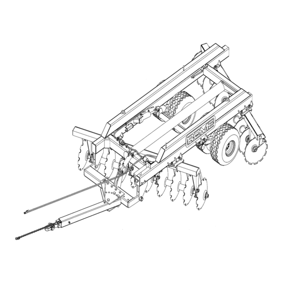
MODEL VIEW / PRODUCT IDENTIFICATION TRW-20... -
Page 4: Introduction
WRITE DOWN PRODUCT IDENTIFICATION NUMBERS. Accurately record all the numbers to help in tracing the machine should it be stolen. Your Rome dealer also needs these numbers when you order parts. File the identification numbers in a secure place off the machine. -
Page 5: General Information
GENERAL INFORMATION TO THE DEALER: Assembly and proper installation of this product is the responsibility of the Rome dealer. Read the manual instructions and safety rules. Make sure all items on the Dealer’s Pre-Delivery and Delivery Check Lists in the Operator’s Manual are completed before releasing equipment to the owner. -
Page 6: Checklists
CHECKLISTS PRE-DELIVERY CHECK LIST After the disc harrow has been completely assembled and lubricated, inspect it to be sure it is in proper operating condition before making the delivery to the customer. The following check list is a reminder of points to inspect. - Page 7 When the disc harrow is transported on the road or highway at night or during the day, accessory lights and devices should be used for adequate warning to operators of other vehicles. Various safety lights and safety devices are available from your Rome dealer. In this regard, tell customers to check local governmental regulations.
- Page 8 CHECKLISTS AFTER-SALE CHECK LIST It is suggested that the following items be checked sometime during the first six months of operation of the disc. Check the entire disc for loose or missing hardware. Check for broken or damaged parts. Make necessary repairs. ...
-
Page 9: Safety Decals
SAFETY DECALS... - Page 10 SAFETY DECALS RED REFLECTOR RED FLO. REFLECTOR AMBER REFLECTOR S.M.V. DECAL...
-
Page 11: Safety Rules
Keep your machine in proper working condition. Unauthorized modifications to the machine may impair the function and/or safety and affect machine life. If you do not understand any part of this manual and need assistance, contact your Rome dealer. - Page 12 SAFETY RULES USE SEAT BELT PROPERLY Use a seat belt when you operate with a rollover protective structure (ROPS) or cab to minimize chance of injury from an accident such as an overturn. Do not use a seat belt if operating without a ROPS or cab.
- Page 13 SAFETY RULES KEEP RIDERS OFF MACHINE Only allow the operator on the machine. Keep riders off. Riders on the machine are subject to injury such as being struck by foreign objects and being thrown off of the machine. Riders also obstruct the operator’s view resulting in the machine being operated in an unsafe manner.
- Page 14 Provide only enough slack in the chain to permit turning. See your Rome dealer for a chain with a strength rating equal to or greater than the gross weight of the towed machine. Do not use the safety chain for...
- Page 15 When transporting machine on a road or highway at night or during the day, use accessory lights and devices for adequate warning to operators of other vehicles. In this regard, check local governmental regulations. Various safety lights and devices are available from your Rome dealer.
- Page 16 SAFETY RULES TOW LOAD SAFETY Stopping distance increases with speed and weight of towed loads and on slopes. Towed loads with or without brakes that are too heavy for the tractor or are towed too fast can cause loss of control. Consider the total weight of the equipment and its load.
- Page 17 SAFETY RULES PRACTICE SAFE MAINTENANCE Understand service procedure before doing work. Keep area clean and dry. Never lubricate, service, or adjust machine while it is moving. Keep hands, feet, and clothing from power-driven parts. Disengage all power and operate controls to relieve pressure. Lower the equipment to the ground.
- Page 18 SAFETY RULES REMOVE PAINT BEFORE WELDING OR HEATING Avoid potentially toxic fumes and dust. Hazardous fumes can be generated when welding, soldering, or using a torch heats paint. Do all work outside or in a well-ventilated area. Dispose of paint and solvent properly. Remove paint before welding or heating: ...
- Page 19 SAFETY RULES AVOID HIGH-PRESSURE FLUIDS Escaping fluid under pressure can penetrate the skin causing serious injury. Avoid the hazard by relieving pressure before disconnecting hydraulic or other lines. Tighten all connections before applying pressure. Search for leaks with a piece of cardboard. Protect hands and body from high-pressure fluids.
- Page 20 Inquire on the proper way to recycle or dispose of waste from your local environmental or recycling center, or from your Rome dealer.
-
Page 21: Preparing The Tractor
PREPARING THE TRACTOR POSITIONING DRAWBAR CAUTION: Avoid personal injury or death due to losing steering control of machine. Always pin drawbar in center position for ALL tractors when transporting machine. Place the drawbar in lower position (offset down) (16-20 in.) from ground to top of drawbar as shown. For four-wheel drive tractors, allow drawbar to swing by moving bolts on support of drawbar one position for field operation only. -
Page 22: Preparing Disc
PREPARING DISC CHECKING & LUBRICATING DISC 1. Inflate all tires to recommended air pressure. (See CHECKING TIRE PRESSURE in MAINTENANCE section). 2. Perform required lubrication. See LUBRICATION section.) 3. Inspect for loose, missing, or damaged parts. Repair if necessary. ADJUSTING RIGID SCRAPERS Using a ratchet or other suitable wrench, adjust scraper blade so curved surfaces match with the curved disc blade. -
Page 23: Notes
NOTES:... -
Page 24: Attaching & Detaching
Provide only enough slack in the chain to permit turning. See your Rome dealer for a chain with a strength rating equal to or greater than the gross weight of the towed... - Page 25 ATTACHING & DETACHING ATTACHING HYDRAULIC HOSES CAUTION: Shut off tractor engine, work levers back and forth to relieve system of pressure. CAUTION: Escaping fluid under pressure can penetrate the skin causing serious injury. Avoid the hazard by relieving pressure before disconnecting hydraulic or other lines.
- Page 26 ATTACHING & DETACHING DETACHING DISC FROM TRACTOR 1. Lower disc completely to the ground with remote cylinder operating lever before unhitching from the tractor, or if disc is to be unhitched in raised position, be sure the transport lockups are installed and the disc is on a firm and level surface.
- Page 27 ATTACHING & DETACHING CHECKING TRANSPORT CONTROL OPERATION 1. Place tractor transmission in “park” and/or set brakes, then start engine and pull back on No. 1 SCV lever until transport cylinders are fully extended. Important: Remove transport locks from the cylinder rods to avoid machine damage. Always remove the left rear transport lock, and then remove front transport lock.
-
Page 28: Attaching & Detaching
ATTACHING & DETACHING CHECKING LEVELING ADJUSTMENT Note: Disc may need readjusting when using a tractor with a different drawbar height. The disc must be level (front-to-rear) when transporting. If the harrow is not level, then use the hydraulic tongue cylinder (before and after) to level the harrow. -
Page 29: Notes
NOTES:... -
Page 30: Transporting Machine
TRANSPORTING MACHINE CAUTION: SAFETY GUIDELINES ONLY TRANSPORT HARROW WITH A TRACTOR. Do not transport harrow by towing with a truck or similar motor vehicle USE CARE WHEN HITCHING THE HARROW TO THE TRACTOR. Hands or fingers can be injured when caught between the hitch and the tractor. ... - Page 31 TRANSPORTING MACHINE POSITIONING TRACTOR DRAWBAR FOR TRANSPORT (FOUR WHEEL DRIVE TRACTORS) 1. Pin tractor drawbar in center down position. Note: Two -wheel drive tractors should be pinned tightly in center position at all times. POSITIONING TONGUE JACK FOR TRANSPORT IMPORTANT: Avoid damage to jack. Make sure tongue jack is installed in storage position on top of drawbar.
-
Page 32: Transporting Machine
In this regard, check local governmental regulations. Various safety lights and devices are available from your Rome dealer. 1. Attach warning light plug to tractor outlet socket. -
Page 33: Operating Machine
OPERATING MACHINE CAUTION: SAFETY GUIDELINES BECOME FAMILIAR WITH THE HARROW AND ITS OPERATION BEFORE RUNNING THE UNIT. Read the Operator’s Manual carefully, regardless of experience. Improper use of the disc could result in serious personal injury. NEVER ALLOW RIDERS ON THE TRACTOR OR HARROW. ... -
Page 34: Operating Machine
OPERATING MACHINE GUIDELINES FOR USE 1. Use recommended size tractor. 2. Decrease the gang angle to zero at which point the gangs are parallel to one another. Wheels are used for transport purposes only. 3. The harrow will plow most level with the front and rear gangs if the disc drawbar is level with the tractor drawbar when the harrow is in the ground in the plowing position. - Page 35 OPERATING MACHINE HYDRAULIC CONTROL The disc can be raised onto the transport assembly by operating the hydraulic control unit. Extending the hydraulic cylinder will raise disc and lower the wheels for transporting and turning. SCRAPER ADJUSTMENT Each scraper should be adjusted so that it does not come in contact with the disc blade as the blade turns, but be slightly closer at the point so that trash cannot build up between the scraper and the disc blade.
- Page 36 OPERATING MACHINE PREPARING TO OPERATE IN FIELD 1. Remove the cylinder transport lock from cylinder and store in field position. Follow safe procedures in the ATTACHING & DETACHING section. CAUTION: Keep all persons away from the disc when raising or lowering the disc. 2.
- Page 37 OPERATING MACHINE ANGLING FRONT AND REAR GANGS Changing the angle of the front or rear gangs will affect penetration of gangs and mixing and covering of crop residue. By changing the gang angle, the operator can adjust for different soil and trash conditions.
- Page 38 OPERATING MACHINE REAR GANG SIDE ADJUSTMENT The rear gang of the disc harrow can be adjusted from side to side. If the rear gang is moved to the left, it increases the amount of soil being thrown into furrow. If the rear gang is shifted right, it will decrease the amount of soil being thrown into the furrow.
- Page 39 OPERATING MACHINE TORSION BAR ADJUSTMENT The leading discs on a wheel-offset disc harrow tend to plow deeper thanks to the trailing discs. Incorporated into the design of the offset harrow frame assembly is a feature that helps compensate for this tendency. This feature is the torsion bar. The torsion bar adjusting nut permits tension to be placed on the frame, which lifts up the outside leading ends of the gang carriers to better level the...
- Page 40 OPERATING MACHINE POSITIONING THE DRAWBAR ON OFFSET BAR TO REDUCE TRACTOR SIDE DRAFT The fact that the disc is trying to rotate counterclockwise must be compensated for by shifting the drawbar plates on the offset bar to the left of the centerline to make the harrow heavier on the right side of the centerline as it is pulled through the ground.
- Page 41 OPERATING MACHINE ADJUSTING SIDE DRAFT...
- Page 42 OPERATING MACHINE ADJUSTING UNEVEN GANG PENETRATION In certain soil conditions, less penetration on left front and/or right rear gang carriers may occur. The following adjustments can be made to equalize disc blade penetration: 1. Move drawbar to left to reduce force against front gang disc blades.
- Page 43 OPERATING MACHINE SET DRAWBAR ANGLE The drawbar can be positioned so disc will trail directly behind tractor or be offset in one of several positions. The harrow may be moved laterally behind tractor by moving drawbar plates on offset bar. First, remove the bolts through offset bar, slide plates to right or left, and replace bolts.
-
Page 44: Lubrication
LUBRICATION LUBRICANT STORAGE Your equipment can operate at top efficiency only if clean lubricants are used. Use clean containers to handle all lubricants. Whenever possible, store lubricants and containers in an area protected from dust, moisture and other contamination. Store containers on their side to avoid water and dirt accumulation. LUBRICATE GANG BEARINGS Use medium consistency pressure grease. -
Page 45: Maintenance
MAINTENANCE SAFETY GUIDELINES CAUTION: BEFORE SERVICING THE HARROW, ALWAYS: 1. Lower the harrow to the ground. 2. Shut the tractor off. 3. Lock the tractor’s parking brake. 4. Remove the key. INADVERTENT OR UNINTENTIONAL MOVEMENT OF THE HARROW WHILE WORKING AROUND THE DISC GANGS COULD RESULT IN SERIOUS OR PERSONAL INJURY. - Page 46 Place bearings, seals, caps, washers, and nuts in clean container and clean with kerosene or other solvents. Inspect the bearings and seals. If they are not in satisfactory condition, replace them with new parts available from your Rome dealer. Clean inside of hubs. ...
- Page 47 DISC GANGS (TRCW-20 & TRCW-24 HAVE 2 ½” GANG AXLES - 20” DISC SPACING) All nuts and bolts must be kept tight. Special attention must be given to keeping the axle nuts tight.
- Page 48 MAINTENANCE REMOVING HYDRAULIC CYLINDER CAUTION: Escaping fluid under pressure can penetrate the skin causing serious injury. Avoid the hazard by relieving pressure before disconnecting hydraulic or other lines. Tighten all the connections before applying pressure. Search for leaks with a piece of cardboard. Protect hands and body from high-pressure fluids.
- Page 49 Reassemble gangs so curved surfaces of spools and disc blades match (bold arrows). GANG AXLE NUT WRENCHES Tightening of gang axle nuts using Rome offset gang axle nut wrenches is easier and safer. These (2) two axle nut wrenches, Rome Part...
- Page 50 MAINTENANCE TIGHEN GANG AXLE NUTS - 2 ½” GANG AXLE CAUTION: Wear gloves and other safety equipment to avoid injury. Oil threads on axle and using the axle nut wrenches provided, tighten the axle nuts as tightly as possible. For best results and added leverage, place an (8) eight or (10) ten foot length of 2 inch pipe on each axle nut wrench to serve as an extension of the handle and hit it with a hammer.
- Page 51 MAINTENANCE ATTACHING DISC GANGS TO STANDARDS CAUTION: Use suitable lifting devices or support stands to prevent disc from falling. Block disc gang when not rolling it into place. Wear gloves and other safety equipment to avoid injury. Where lifting facilities are available: 1.
- Page 52 MAINTENANCE SERVICES TIRES SAFELY CAUTION: Explosive separation of a tire and rim parts can cause serious injury or death. Do not attempt to mount a tire unless you have the proper equipment and experience to perform the job. Always maintain the correct tire pressure. Do not inflate the tires above the recommended pressure. Never weld or heat a wheel and tire assembly.
- Page 53 MAINTENANCE TIRE PRESSURE CHART TIRE SIZE LOAD MAX TIRE SPEED MAX LOAD@ SUGGESTED INDICATOR INFLATION PSI 7.5 X 16 6 PLY 6 PLY 25 MPH 1930 LBS @ 36 PSI 7.5 X 16 10 PLY 10 PLY 25 MPH 2680 LBS @ 60 PSI 9.5L X 15 8 PLY 8 PLY 25 MPH...
-
Page 54: Storage
5. Apply a good rust preventive, such as paint or a heavy coating of grease, to disc blades. Paint is available from your ROME dealer. 6. Inspect for worn and damaged parts. Replace them now to make sure disc will be ready for next season. -
Page 55: Assembly
ASSEMBLY CAUTION: SAFETY GUIDELINES WEAR PROPER ATTIRE WHEN ASSEMBLING HARROW. Always wear relatively tight and belted clothing to avoid entanglement in equipment. Wear sturdy, rough-soled work shoes and protective equipment for eyes, hair, hands, hearing and head. HANDLE THE DISC GANG COMPONENTS WITH CARE. - Page 56 ASSEMBLY CHECK ALL PARTS ON PACKING LIST For Export Shipment assembly procedure, follow steps 1 through 10. For Domestic Shipment assembly procedure, follow steps 3 through 10. Note: Use the parts diagrams and listings in the Parts Manual to help facilitate assembly of the disc harrow. STEP 1: ASSEMBLING GANGS For shipping purposes, the bearings, spacers, axle washer, bumper washer, axle nuts, and axle nut locks are shipped bundled together.
- Page 57 ASSEMBLY STEP 1: ASSEMBLING GANGS - CONTINUED…. F. Refer to the Illustration and continue to slide the discs, spacers, and bearings down the axle exactly in the order shown. Important: Make sure that concave and convex faces on the washers, bearing assemblies, and disc spacers coincide with the faces of the discs.
- Page 58 ASSEMBLY STEP 2: INSTALLING GANGS ON GANG CARRIERS Where lifting facilities are available: A. Position front gang assembly with concave side of discs to right, as viewed from the rear. B. Position rear gang assembly with concave side of discs to left, as viewed from the rear. C.
- Page 59 ASSEMBLY STEP 5: INSTALLING WHEEL ASSEMBLIES The wheel and tire assemblies should be attached to the hubs with studs and lug nuts (8 or 10 per hub) provided on hub assemblies. Wheel bearings have been properly adjusted and lubricated at the factory. When you mount the wheel assembly onto the hubs, make sure the valve stem is to the outside (lug bolt side).
- Page 60 STEP 10: INSTALLING HYDRAULIC CONTROL GROUPS A. There are three hydraulic cylinders on the TRCW-20 & TRCW-24. Two of these are transport cylinders. The base end of these cylinders attach to the frame of the TRW. The rod end attaches to the cylinder bracket on the transport.
- Page 61 ASSEMBLY HS-TRCW-20 & TRCW-24 HYDRAULIC SCHEMATIC REF. PART PART NAME REQ’D NUMBER 5005453 HOSE CLAMP HALVE ¾” O-RING BOSS X ½” MJIC 90 5000618 HOSE ASSEMBLY, 74” 3059764 HOSE ASSEMBLY, 90” 3059765 HOSE ASSEMBLY, 126” 3059766 HOSE ASSEMBLY, 140” 3059767...
-
Page 62: Assembly
ASSEMBLY ATTACHMENT ASSEMBLY GENERAL: CAUTION: Wear protective clothing and safety equipment appropriate to the job. Work safely to avoid injury and observe all safety messages. Read all assembly instructions and carefully observe illustrations! INSTALL SAFETY CHAIN Attach safety chain by pinning shackle through hole in bracket on left front side of the drawbar assembly. Secure with the shackle pin and cotter pin. -
Page 63: How To Order Parts
Also, please indicate whether shipment is to be by truck, UPS, air courier, or by other means. ONLY ROME PARTS GIVE ROME PERFORMANCE The same quality and craftsmanship that have made Rome products famous throughout the world are built into all Rome replacement parts... -
Page 64: Warranty
No employee of Rome or any other party is authorized to make any warranty in addition to those made In this agreement. -
Page 65: Limited Warranty & Registration Form
MISSOURI MACHINE & PLOW, LLC. WARRANTY 1 YEAR LIMITED WARRANTY & OWNER REGISTRATION FORM MISSOURI MACHINE & PLOW, LLC. PO BOX 48, CEDARTOWN, GA, 30125 USA Product Name:____________________________________________________ Model Number:____________________________________________________ Serial Number:____________________________________________________ Owner/Purchaser Name:_____________________________________________ Address:__________________________________________________________ City:____________________________State:_________Zip:________________ Phone: (___)_____________________ Owner/Purchaser Name:_____________________________________________ Address:__________________________________________________________ City:____________________________State:_________Zip:________________ I have checked this equipment and reviewed the Owner’s Manual and safe...
Need help?
Do you have a question about the TRCW-20 and is the answer not in the manual?
Questions and answers