Table of Contents
Advertisement
Quick Links
TEMPERATURE
AND HUMIDITY
TRANSDUCER
PCE-P18
USER'S MANUAL
PCE Americas Inc.
711 Commerce Way
Suite 8
Jupiter
FL-33458
USA
United Kingdom, SO31 4RF
From outside US: +1
Tel: (561) 320-9162
Fax: (561) 320-9176
info@pce-americas.com
info@industrial-needs.com
www.pce-instruments.com/us
www.pce-instruments.com/english
www.industrial-needs.com
PCE Instruments UK Ltd.
Units 12/13
Southpoint Business Park
Ensign way
Hampshire / Southampton
From outside UK: +44
Tel: (0) 2380 98703 0
Fax: (0) 2380 98703 9
1
Advertisement
Table of Contents

Summary of Contents for PCE Instruments PCE-P18
- Page 1 PCE Americas Inc. PCE Instruments UK Ltd. 711 Commerce Way Units 12/13 Suite 8 Southpoint Business Park Jupiter Ensign way FL-33458 Hampshire / Southampton United Kingdom, SO31 4RF From outside US: +1 From outside UK: +44 Tel: (561) 320-9162 Tel: (0) 2380 98703 0...
-
Page 3: Table Of Contents
Contents 1. AppliCAtion ................5 2. trAnsduCer set ..............7 3. BAsiC requirements, operAtionAl sAfety ....7 4. instAllAtion ................7 4.1. Way of fixing ................7 4.2. External connection diagrams ..........9 5. serviCe ..................11 5.1. Power-on messages of the P18D transducer ...... 11 5.2. -
Page 5: Application
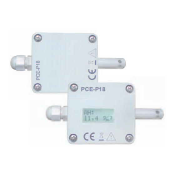
1. APPLICATION The PCE-P18 transducers are the devices destined for the continuous measurement and conversion of relative humidity and ambient temperature into a digital form and into a voltage or cur-rent standard signal. The transducers are fixed on a wall. Programming of the transmitters is possible via the RS?-485 interface. - Page 6 Fig. 2. Overview of the P18 and P18D transducers with the probe on the wire 0,5 m.
-
Page 7: Transducer Set
2. trAnsduCer set − Transducer 1 pc − User’s manual 1 pc − Warranty card 1 pc 3. BAsiC requirements, operAtionAl sAfety In terms of operational safety, the transducer meets the requirements of the EN 61010-1 standard. Comments concerning safety •... - Page 8 Fig. 3. Overall dimensions of the P18(D) transducer mounting holes Fig. 4. Lay-out of mounting holes of the P18(D) transducer...
-
Page 9: External Connection Diagrams
4.2. external connection diagrams The P18(D) transducer version P18(D)-1XXX or P18(D)2XXX has 8 connecting terminals, version P18(D)-0XXX has 4 terminals (ver- sion without analog outputs). Access to the terminals is possible after removing the cover of the transducer housing. You should use a multi- conductor round wire with external diameter from 3.5 mm up to 6 mm for electrical connections. - Page 10 Transducer without analog outputs Transducer with current outputs Transducer with voltage outputs Fig. 6. Wiring diagram of the P18(D) transducer with analog outputs Use shielded cable for supply and output signals in environ- ments with high levels of interference. The shield must be connected to the nearest PE point from the feeder side.
-
Page 11: Service
5. serviCe The P18D transducer is equipped with a display field 8x2 characters with illumination and one capacitive button located on the housing. The P18 transducer is not equipped with a display or a button. After connecting the wires, closing and servicing the housing, and connecting to the supply, the transducer is ready to work with manufacturer’s settings (Tab. -
Page 12: Description Of The P18D Transducer Readout Field
5.2. description of the p18d transducer readout field The illuminated character LCD is a readout field in the trans- ducer P18D. The illumination is turned on after switching on the supply and after the capacitive button on the housing is pressed. The illumina- tion is automatically switched off after 30 sec. -
Page 13: Functions Of The P18D Transducer Capacitive Button
Type of the displayed value in the bottom line of the LCD - dew-point Type of the displayed value in the bottom line of the LCD - absolute humidity The indicator of the measuring value from the sensor Automatic mode of measurement results presentation - a type of displayed value is automatically switched every 3 seconds in the following order: temperature →... -
Page 14: Programming Parameters Menu Of The P18D Transducer
Capacitive button is used to: • switch the display illumination on • change the presentation mode of the measurement results - holding the button for about 2 seconds switches from automatic mode to manual mode or inversely • change the type of displayed values in the manual mode of presen- tation of the measurement results - pressing the button for a short time changes the displayed value. -
Page 15: Functions Of The P18(D) Transducer
Confirmation Measurement of changes Application 5 seconds of changes 5 seconds 5 seconds Mode programming Baud rate programming Address programming 5 seconds 5 seconds increase/ increase/ increase/ decrease decrease decrease the value the value the value decreasing the value increasing the value Fig. -
Page 16: Calculated Values
5.5.1. Calculated values Based on the measurement of a temperature and relative humidity, the P18D transducer calculates dew-point and absolute humi- dity of the following dependencies. DP → dwe-point: 10000 A RH AH = 2,1668 DP → absolute humidity: 100 ... -
Page 17: Individual Characteristic Of Analog Outputs
(T, RH, DP, AH, wet bulb temperature). The value controlling the analog outputs is defined by the registers, respectively 4015 for the first output and 4016 for the second analog output (Tab. 14). 5.5.3. individual characteristic of analog outputs The P18(D) transducers in the version with analog outputs enable the conversion of measured values into an output signal ba- sed on the strength of individual linear characteristic of analog outputs. - Page 18 The configuration of the individual characteristic of analog outputs amounts to the introduction of suitable values X1, X2, Y1, Y2 in corresponding registers to them from the range 4007 – 4014 Tab. 3. The values introduced in these registers must be integral values corre- sponding to the set point values multiplied by the value 100.
-
Page 19: Support Of A Sensor Heater
5.5.4. support of a sensor heater The sensors used in the P18(D) transducers are equipped with internal heating elements to allow faster release of water molecu- les from the sensor being flooded or working a long time in highly hu- mid environments. -
Page 20: Default Settings
5.5.5. default settings The Table 4 shows the standard settings of the P18D transdu- cer. The settings can be restored via the RS-485 interface after writing the value „1” to the registry 4020. Table 4 Standard value Para- Parameter meter P18D-0XX, P18D-1XX, P18D-2XX,... -
Page 21: Rs-485 Interface
Value control- 4015 ling the first analog output. Value control- 4016 ling the second analog output. Custom confi- 4019 guration 6. rs-485 interfACe The P18(D) programmable digital transducers have a serial link RS-485 for communication in the computer systems and with other de- vices that serve as a Master. - Page 22 Output of the interface line is shown in Fig. 6. It is required to con- nect the lines A and B in parallel with their equivalents in other devices to obtain the correct transmission. The connection must use a shielded wire.
-
Page 23: Description Of The Modbus Protocol Implementation
6.2. description of the modBus protocol implementation The implemented protocol is compliant with the PI-MBUS-300 Rev G specification of Modicon. Set of parameters of the P18D transducer serial link in the MODBUS protocol: • Transducer address 1..247. • Baud rate: 4800, 9600, 19200, 38400, 57600, 115200 [b/s]. •... - Page 24 Readout of n-registers (code 03h) example 1. Readout of 2 registers, starting with the register address 1D4Dh (7501) float (32-bit), (register values 25.68, 20.25.) Request: Table 5 Register address Number of registers Device CRC check- Function address 5270h Response: Table 6 Value from the register Value from the register Device...
- Page 25 Writing n-registers (code 10h) example 3. Writing the value 78h (120) and the value 4h (4) to the regi- sters FA1h, FA2h (4001, 4002) Table 9 Request: Register Register Num- value value vice Fun- Register Number of ber of 4001 4002 ction address...
-
Page 26: Map Of The Registers
6.4 map of the registers In the P18D transducer, data are placed in 16 and 32-bit registers. Process variables and transducer parameters are placed in the address area of registers in a way depended on the variable value type. Bits in 16-bit registers are numbered from the youngest to the oldest (b0 …... -
Page 27: Registers For Writing And Readout
Table 14 6.5 registers for writing and readout Name Range Description 4000 Identifier P18 device identifier P18D device identifier 4001 Address 1...247 Device address 4002 RS-485 0...5 Description baud rate 4800 bit/s 9600 bit/s 19200 bit/s 38400 bit/s 57600 bit/s 115200 bit/s 4003 RS-485 0...3... - Page 28 4004 Confir- 0...1 Description mation of trans- No change mission parameters Confirmation of changes changes 4005 Averaging 6...3600 Averaging time of the mea- surement [s] time 4006 Erasing 0...1 Description the extre- No change Erasing the min. and max. values 4007 X1 of out- -32768 Value controlling out-...
- Page 29 Dew-point Absolute humidity Wet bulb tempera- ture 4016 Value 0...3 Description controlling 2 analog Temperature output. Relative humidity Dew-point Absolute humidity Wet bulb tempera- ture 4017 Status -32768 Transducer status. Shows ...32767 the current state of the trans- ducer and the hardware con- figuration.
- Page 30 Bit12 not used Bit11 Indicator of switching the heater on Bit10 Indicator of erasing the extremes, writing the value 1024 (400h) erases the status bit Bit9 Temporary commu- nication parameters are set (shorten jum- per „ZW”) Bit8 LCD display error Bit7 Error reading the va- lue from the sensor...
- Page 31 Bit2 results averaging in- terval has ended Bit1 The transducer is equi- pped with the analog outputs - voltage. Bit0 The transducer is equi- pped with the analog outputs - current. 4018 Software 1...999 Software version x100 version 4019 Custom 0...31 Bit0 Value...
- Page 32 4020 Default 0...1 Description settings no change przywraca parametry fabryczne 4021 Controlling Description the heater switching a heater off permanent switching a heater on displaying remaining time of a heater swit- ched on switching a heater on for Xn seconds (Xn - 32768 value from the range 60...32768 )
-
Page 33: Registers For Readout
6.6 registers for readout Table 15 7000 7500 P18(D) device identifier 7002 7501 Measured temperature 7004 7502 Measured relative humidity 7006 7503 Calculated dew-point 7008 7504 Calculated absolute humi- dity 7010 7505 min T Min. of temperature 7012 7506 max T Max. - Page 34 7020 7510 max DP Max. of dew-point 7022 7511 min AH Min. of absolute humidity 7024 7512 max AH Max. of absolute humidity 7026 7513 Wet bulb temperature 7028 7514 Water vapor pressure Table 16 shows the registers of measuring values of the P18D transdu- cer working in the registers 7000 and 7500 compatibility mode with the P14W transducer Table 16...
- Page 35 7002 7501 Measured tempera- ture 7004 7502 Calculated dew-point 7006 7503 Measured relative 7008 7504 humidity 7010 7505 Calculated absolute humidity 7012 7506 7014 7507 7016 7508 7018 7509 min T Min. of temperature 7020 7510 max T Max. of temperature 7022 7511 min DP...
-
Page 36: Emergency Restoration Of Default Parameters
6.7 emergency restoration of default parameters If the communication parameters have been changed and the new configuration is lost, you can use the jumper marked „ZW” on the transmitter’s board to set the temporary communication parameters: • address • baud rate 9600 kb/s •... -
Page 37: Error Codes
7. error Codes The error messages could be displayed on the transducer P18D display during operation. The table below lists the error codes which are possible to be displayed and their reasons as well as the recommended user responses. Information about the existing errors is also available in the P18(D) transducers status register - register 4017. -
Page 38: Accessories
8. ACCessories As a standard, the P18(D) transducer is equipped with a shield of the sensor, destined only for indoors applications. It is recommended to use additional shields of the sensor (interchangeable) for outdoors or indoors applications exposed to the possibility of water vapor condensa- tion, depending of the transducer working conditions. -
Page 39: Technical Data
6. teChniCAl dAtA Basic parameters: - range of relative humidity measurement (RH) 0...100%, without condensation - basic error of humidity conversioni ± 2% of the range for RH = 10...90% ± 3% for the remaining range - hysteresis of the humidity measurement ±... - Page 40 rated operating conditions: - supply 9...24 V a.c./d.c. - power consumption < 0.5 VA - ambient temperature - 20...23...60 - relative air humidity < 95% 0,5 m/s - rate of air flow - preheating time 15 minutes - protection grade ensured by the housing IP 65 - fixing...
-
Page 41: Ordering Code
7. ordering Code Table 10 p18(d) - X XX X Analog outputs - sensor: without outputs, sensor on the housing current 4...20 mA, sensor on the housing voltage 0...10V, sensor on the housing without outputs, probe on the wire 0,5 m current 4...20 mA, probe on the wire 0,5 m voltage 0...10V, probe on the wire 0,5 m version:... - Page 44 P18-09C PCE Americas Inc. PCE Instruments UK Ltd. 711 Commerce Way Units 12/13 Suite 8 Southpoint Business Park Jupiter Ensign way FL-33458 Hampshire / Southampton United Kingdom, SO31 4RF From outside US: +1 From outside UK: +44 Tel: (561) 320-9162...
Need help?
Do you have a question about the PCE-P18 and is the answer not in the manual?
Questions and answers