Table of Contents
Advertisement
Quick Links
Advertisement
Table of Contents

Related Manuals for Jeti Duplex DC16


Summary of Contents for Jeti Duplex DC16
- Page 1 Certification Exhibit FCC ID: ONTJETIDC16US IC: 10491A-JETIDC16US FCC Rule Part: 15.247 IC Radio Standards Specification: RSS-210 ACS Project: 12-2095 Manufacturer: Esprit Model Model: JETIDC16US User Manual 3998 FAU Blvd. Suite 310 Boca Raton, FL 33431 Tel: 561-961-5585 Fax: 561-961-5587...
- Page 2 This by Jeti Model in the Czech Republic. This system has been reliably transmitter was created with the goals of maximum utility, simple used for many years.
- Page 3 computer radio control system Large Memory – 4GB memory space for storing models, sounds, and 1.2 Table of Contents telemetry data. To make navigation faster, the DC-16 transmitter Instruction Manual USB Connector – convenient connection to your PC. Fast firmware & has been divided into 5 basic groups: sound upgrades, telemetry data downloads.
-
Page 4: Technical Support
Third party transactions are not covered by this warranty. Proof of purchase is required for warranty claims. Repair or replacement decisions are at the sole discretion of Jeti Model CZ or an authorized service provider. This warranty does not cover cosmetic damage or damage due to an accident, misuse, abuse, negligence, commercial or research use, or modification of or to any part of the product. -
Page 5: System Specifications
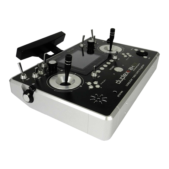
• Wireless Trainer Module Internal Memory microSD 4GB • Wide Assortment of 4 to 18-channel Duplex Receivers Telemetry • Wide Assortment of Jeti Telemetry Sensors PC Connection USB mini Graphic Display 3,8" - 320x240px Operational Temperature -10 up 60 °C... - Page 6 computer radio control system 4 Description of Transmitter 4.1. Control Identification Right Stick 1, 2 – the DC-16 Transmitter Supports Modes 1-4, see Control Sticks -> mode change Left Stick 3, 4 the DC-16 Transmitter Supports Modes 1-4, see Control Sticks ->...
- Page 7 computer radio control system 4.2. Assembly Identification Battery Connector Transmitter Battery Pack PPM Output Connector Left Gimbal Assembly Right Gimbal Assembly...
- Page 8 computer radio control system If you have installed optional sticks with switch or 4.3 Control Stick Assembly Warning: button ends; make sure that while adjusting the stick length you observe the wires that pass through Note: When handling with back cover removed always the stick shaft and through the gimbal opening in switch-off the transmitter and disconnect the order to prevent damaging the connecting cables.
- Page 9 computer radio control system Loosen both machine screws securing the control stick decrease. By turning the screw clockwise, you will tighten assembly. spring tension. As a result the moving resistance of the control stick will increase. Adjust (rotate) to desired position. Securely tighten both machine screws securing the control stick Reconnect transmitter battery pack and reinstall radio back assembly.
- Page 10 computer radio control system 4.3.5. Transmitter Mode Switch The DC-16 transmitter allows you to switch between Mode 1, 2, 3 and 4 stick configurations with just few simple steps. In order to do some of these, the stick control assemblies will need to be swapped. Switch-off the transmitter and remove the 10 screws that secure the radio back cover.
- Page 11 computer radio control system 4.3.6. Transmitter Gimbals with Switch or Button X Y S Installation If you want to operate the DC-16 transmitter using the optional stick end switch or button functions, you must purchase one or more of these separately: •...
- Page 12 computer radio control system Remove both machine installation screws for each of the you observe the wires that pass through the stick shaft control stick assemblies. and through the gimbal opening in order to prevent Carefully remove both control stick assemblies. Gently pull in damaging the connecting cables.
- Page 13 (3 wires X, Y, S ). Pay close attention to the wire lengths. Connect the longest wire as the first one from the outside of the One of the most important features of a Jeti transmitter is the switch transmitter (3 connectors X, Y, S).
- Page 14 computer radio control system Switch Exchange: Digital Trims Switch-off the transmitter and remove the 10 screws that secure Transmitter gimbals are used for controlling the basic flight the radio back cover. Next, remove the radio back cover. functions like throttle, roll(aileron), pitch(elevator), and yaw(rudder). Be sure to disconnect the transmitter battery pack Immediately under the transmitter gimbal sticks you can see four connector.
- Page 15 computer radio control system 4.6.2. Battery Replacement 4.6 Transmitter Battery Pack Should you decide to replace the transmitter battery, please follow The DC-16 transmitter is powered by a Li-Ion type battery pack and these steps: comes equipped with its own built-in advanced battery Switch-off the transmitter and remove the 10 screws that management and charging circuit.
- Page 16 computer radio control system 4.7. PPM Output Connector 4.8. Handling The DC-16 transmitter can be comfortably carried by holding it for The PPM output is accessible via connector labeled „B“. This the antenna cover/handle as shown on the picture. connector features the non-stabilized battery voltage output in the range of 3,2V - 4,2V (max.
- Page 17 The receivers can be interconnected via an intelligent synthesizer, for instance the JETI Enlink, or the basic control functions can be divided between two independent receivers. In this mode one part of a...
- Page 18 computer radio control system 6 Transmitter Powering ON/OFF 6.2. Transmitter Turning-OFF The transmitter is switched-off by pressing the „Power“ main 6.1. Transmitter, Powering-ON button. Before complete power-down is achieved you will be asked for additional confirmation. In case of an emergency, a fast turn-off Switching-on is achieved by pressing and holding the „Power“...
- Page 19 computer radio control system items or alarms, the number of available pages will automatically 7 Initial switching-on increase or decrease as needed. Turn the transmitter on by pressing and holding the „Power“ button In this example, the desktop page displays the following for a couple of seconds and then press the "F5 (Yes)"...
- Page 20 computer radio control system 7.2. Navigation in the Menu To navigate within the transmitter menus, use the following buttons: The „menu“ button allows you to switch between the main display and the transmitter‘s main menu. Also, If you push this button while turning the 3D Control Selector to edit values, the values can be changed faster.
- Page 21 computer radio control system 7.3 Model Set-up Guide Notice: For safety reasons we recommend first removing the propeller. In this section we will guide you, step by step, through the process of Switch-on the transmitter. In the main creating a new model airplane and helicopter. Each step of the guide display push the key „menu“.
- Page 22 computer radio control system This page displays the flight control Bind transmitter with the receiver, see chapter 8.4 Receiver->Binding. functions and their transmitter switch Once your transmitter has been bound with the receiver and you have assignments. Here you can verify that your re-applied power to the receiver, the last setup phase is the tuning of flight control functions are correctly assigned your servo output functions.
- Page 23 computer radio control system Switch-on the transmitter. In the main Note: When setting up your spoilerons be sure that the ailerons still display push the key „menu“. Select the have enough travel to control your airplane when the spoilerons are deployed. In this menu the „(Sym) F1“ button will link or item „Model“...
- Page 24 computer radio control system When you create a new helicopter model you are required to define The screen will display a question which the swash plate configuration for the model. Please refer to your asks if you really want to create and activate helicopter’s instructions and verify that you have the correct swash the new model.
- Page 25 computer radio control system 7.3.3 General Switch-on the transmitter. In the main The DC-16 transmitter is not only equipped with the assistants for display push the key „menu“. Select the airplanes or helicopters, but it also has a „General“ assistant which item „Model“...
- Page 26 computer radio control system The „Servo Setup“ menu is where you In the „Function Assignment“ menu can set all of your servo neutral positions, use the „F3(Add)“ button to create all of servo output throw limits, servo reversing, your desired functions. Then you can assign delay etc.
- Page 27 computer radio control system To assign a switch for the activation and Note: You should Mechanically adjust all of your servo arms and servo deactivation of the free mixer press the linkages to be as close to neutral or center as as possible so that „F4(Edit)“...
-
Page 28: Technical Data
Programming EXT - input for telemetry sensors. If you want to connect more than one telemetry sensor then use the JETI EXPANDER E4. You can Support of satellite receivers Rsat „daisy-chain“ several of the E4 Expanders to support many, many Maximum output power [dBm] sensors. -
Page 29: Fail Safe
If not, check your model’s antenna installation first. If the test is still 8.4. Binding not successful don´t fly the equipment and contact your retail shop or one of the Jeti authorized service centers. In order to achieve communication between transmitter and receiver you must bind them. During this process the transmitter 8.6. - Page 30 computer radio control system Each receiver channel can be configured to one of the modes described above. We recommend that you setup „fail safe“ positions for every output which enables your model to stay in a stable condition. For instance, the elevator and rudder in neutral positions, electric motor switched-off, gas engine idling, spoilers extended.
-
Page 31: Main Menu
computer radio control system 9 Main menu The numbers on the left side of the display shows the sequence You reach the basic menu from the main display by pressing the of the menu items. „menu“ key. The main menu is divided into a basic and a user section. In the basic menu, the menu items are divided into sub-menus. - Page 32 computer radio control system Model selection 9.1. Model In the list of models, select the required model and confirm it by pressing the „3D button“ or „F1(Ok)“ button. You will be prompted The „Model“ menu contains basic functions for working with your to confirm loading of the selected model.
- Page 33 computer radio control system 9.1.2 New Model Note: If you would like to make set-up changes in an existing Selecting this menu item starts the new model creation assistant. model, you should first make a copy of the original The assistant begins creating a new model profile as soon as you setup.
- Page 34 computer radio control system will enter the model name that you want the transmitter to use when 9.1.3 Basic configuration- AIRPLANE the model is stored in the transmitter‘s memory. The maximum In this menu you will setup the wing configuration, tail type, available space for a model name is 12 characters, including spaces.
- Page 35 computer radio control system 9.1.4 Basic Configuration - HELICOPTER Tail Assembly The following tail option are available: Type Description Standard tail assembly with one horizontal control Standard 1H1V (elevator) and one vertical control (rudder) V-tail 2H Traditional V-tail Tail assembly with two elevator servos and one Ailvator 2H1V rudder servo Swash Plate Type...
- Page 36 computer radio control system • „Mechanical“ - this swash plate type uses a single servo for Governor each flight function. This is the swash plate type to select if you are In some helicopter setups a governor function is used for motor using a flybarless controller.
- Page 37 computer radio control system 9.1.6 Basic Configuration-GENERAL Flight function Renaming By editing each „Function“ item you can rename a flight function Number of Motors in the Model from its original name to any name that you choose. This is where you select the number of motors in your model. It is Assignment of a Control Element to a Flight Function possible to select 0-4 motors.
- Page 38 computer radio control system of these items you will enter the menu: „Select control input“, see Note: The initial assignment is carried out in accordance with your chapter 9.7. The assignments can easily be verified by the graphic selected transmitter mode. If the initial assignment is incorrect found beside the control element description in the „Trim “...
- Page 39 computer radio control system 9.1.9 Servo Setup Assignment of Transmitter Output Functions to Receiver This menu is for the additional tuning of output functions of the Channels transmitter->receiver channels->servos. The assignment of a Select the required receiver channel and press the „3D button“. transmitter output function to a receiver channel is shown in the Now you can choose which function you want assigned to the upper part of the menu (first item below the menu description).
- Page 40 computer radio control system Advice: When building a model try to mechanically adjust the Servo Reversing neutral positions as perfectly as possible. If you are Use this item to reverse the direction of a servo’s travel. going to use a high „Center (Subtrim)“ value in order to Delay of positive/negative set-up a servo neutral, the resulting servo throw will be This item allows you to delay the servo channel‘s travel time...
- Page 41 computer radio control system Up to 10 different flight modes are available for every single model. 9.2. Fine Tuning 9.2. Fine Tuning Each one of these flight modes can be named differently for instant - Extended program functions for fine tuning your models recognition.
- Page 42 computer radio control system Naming Flight Modes Advice: If no flight mode is required, do not change the pre-set configuration. We recommend naming flight modes according to their function, for example: Take Off, Soaring, Autorotation…. Flight mode names/labels can be easily edited at any time. Flight Mode Delays The time delay function can help smooth the transition from one flight control state to another.
- Page 43 computer radio control system column to help you determinate the ON or OFF switch position for each flight mode. • Check Mark – ON Position • X Mark – OFF Position When the flight mode is activated the flight mode name can be seen the top of the desktop screen.
- Page 44 computer radio control system This is useful when you are setting up a new model from a copied Advice: For a maiden flight we recommend using larger trim model and you want different flight modes. steps. After familiarizing yourself with your model’s behavior you can switch to smaller steps for finer Advice: After you make a configuration change or perform a...
- Page 45 computer radio control system Pressing the “F1 (Sym.)” turns ON/OFF the lock which allows each output to be adjusted either together (symmetrically), or independantly. Trim Travel Global or Separate Setting The servo trim position for each function output can be set either collectively for all flight modes by selecting the “G-(globe symbol)”...
- Page 46 computer radio control system Expo/Dual Rates Travel Setting Percentage of travel Every switch position can define a different function and Exponential rate setting exponential value. Any change made to the settings can be directly Assignable switch option observed on graphic interface Graphic interface Dual/Triple rate setting is defined by percentage of the travel higher number increases travel, a lower number decreases travel.
- Page 47 computer radio control system 9.2.5 Programmable Function Curves and in the second mode it is disabled). There are some specific conditions where setting this option for one function has an effect in Function curves define the relationship between the actual position another function.
- Page 48 computer radio control system The function curve can selected from the existing list or from custom, previously modified options. Available Options: Standard Linear values, set In/Out point Constant Constant value, set point All of the points can be moved in both horizontal and vertical directions.
- Page 49 computer radio control system Global or Separate Function Curve Setting 9.2.6 Aileron Differential The function curve configuration for all channels can be set The aileron differential function reduces the downward travel of the collectively for all flight modes by selecting the “G-Global (globe)” aileron(s) to help eleminate any adverse yaw tendencies in rolling symbol or you can set individual function curve settings in each maneuvers.
- Page 50 computer radio control system the servos need to be adjusted independantly, use the “F1 (Sym.)” button to unlock the servo travel for adjusting the individual values in the selected menu line. Tuning of Aileron Differential You can now assign a proportional control and the adjustment rate. When moving the control, the differential rates are updated accordingly: up-rate is increased and the down-rate is decreased depending on the adjustment rate and position of the control.
- Page 51 computer radio control system 9.2.8 V-Tail Mix 9.2.9 Delta/Elevon Mix If your model is equipped with a V-Tail, The two basic tail functions The Delta/Elevon Mix uses two servos for the control of both the (rudder and elevator) are mixed to control the tail of the airplane. elevator and aileron functions.
- Page 52 computer radio control system each servo. If the servos need to be adjusted independantly, use the movement of the control surfaces during the change. Increasing the “F1 (Sym.)” button to unlock the servo travel for adjusting the number on the positive side “+” slows the deployment while individual values in the selected menu line.
- Page 53 computer radio control system Actual values of airbrake rates. T h e v a l u e s shown depend on adjustments m a d e Butterfly Tuning m e n u (see below). Ailerons/Flaps Adjustment Butterfly Tuning menu In the Ailerons/Flaps Adjustment menu you can set all the travel Screen of the Butterfly menu allows you to fine tune all braking needed for butterfly braking (for the flaps and ailerons).
- Page 54 computer radio control system button to exit the free mix screen. If you need to make any changes 9.2.11 Free Mixes simply highlight the desired free mix and press the “F4 (Edit)” The Free (programmable) mixes are used to make a second or „slave“ button to reach the advanced settings menu for that free mix.
- Page 55 computer radio control system Free Mix Multiple Servo Settings If the mix uses more than one output function as the slave then the “Output Mix” menu will appear. This menu allows you to edit the settings for the individual slave servos (S1-S4). Free Mix Directional Positive/Negative Movements Once the free mix function is created you can edit the advanced settings menu so that the mix will either add to or reduce a slave...
- Page 56 computer radio control system Free Mix Trim Settings This item allows you to enable or disable whether trim functions will influence the free mix or not. Free Mix Control by Dual Rates With this item you can activate or deactivate the “Slave Dual-Rate” function for the free mix.
- Page 57 computer radio control system The throttle limiter also influences mixes where the throttle acts as 9.2.13 Throttle Limiter the source. The trim function is not influenced by the throttle limiter. If you have several flight modes and all of them have specific throttle If a control device is not assigned, the throttle limiter function is curves, the Throttle Limiter might help you to get the motor's RPM disabled.
- Page 58 computer radio control system Auto-Trim Function 9.3. Advanced Properties Auto-Trim function can be activated using any assigned switch, knob or stick. Once this function has been activated you can trim Advanced programming menu for DC/DS-16. your model using transmitter gimbals. The direction and speed of the trim adjustment is determined by stick movement.
- Page 59 computer radio control system defined (completely off ) throttle position once the assigned switch Switch ON/OFF Points is activated. Any proportional function can be set as a system switch. This menu item enables you to assign the travel percentage at which a desired Throttle Idle Setting function can be turn ON or OFF.
- Page 60 “Student” mode, disables its secondary RF module and uses only the primary RF module to communicate with instructor’s transmitter. Other brands of transmitters can be used by the student with a Jeti Duplex EX 2.4GHz radio system by using a special wireless “Trainer” communication module by Jeti.
- Page 61 Assignment for the input channel from the student’s transmitter. transmitter to the Control function of the instructor’s Mode Selection. transmitter. Binding initialization of the Instructor transmitter‘s primary RF module or special wireless “Trainer” module by Jeti. Channel function assignment. ...
- Page 62 Trainer Mode for Jeti DS/DC-16 as the Instructor Radio properly. Other brands of transmitters can be used by the student with a Jeti Verify that all of the aircraft’s surfaces are correctly controlled Duplex EX 2.4GHz radio system by using a special wireless “Trainer”...
- Page 63 ...
- Page 64 computer radio control system 9.3.4 Logical Switches If you want to have single or multiple transmitter functions which are controlled based upon the condition of other control conditions then setting up a logical switch is the way to go. Each logical switch is ...
- Page 65 computer radio control system Emulating a 3-Position Switch same time they will play at the same time and their sounds will overlay each other. You can use the logic function “Multi” to allow the logic switch to act as a 3-position switch.
- Page 66 computer radio control system Model Time/Reset Timers at Power Up 9.4. Timers/Sensors By pressing F1() button you can choose which timers will be reset - Set up of Timers and Telemetry Sensors after turning on the TX or after selecting the model. By default, all ...
- Page 67 computer radio control system ...
- Page 68 computer radio control system Editing a New Timer switch is triggered. Once started, this type of timer can only be stopped using the„F4(Stop)“ button. Timer Name When you add or change the timer name, the name is automatically Use the „F5(Clr)“...
- Page 69 computer radio control system ...
- Page 70 9.4.2 Alarms If you use the Jeti telemetry system, in this menu you can set your alarm thresholds and choose which sound is played in the alarm condition. The transmitter support both first generation Duplex and Duplex EX alarms.
- Page 71 ...
- Page 72 computer radio control system 9.4.3 Vario Enable an Alarm Located in: „Menu->Timers/Sensors/Vario”. There are two types of Using the „3D button“, select „Enabled“ and press to enable the acoustic signalling. The first one is controlled directly by the sensor's alarm and display the alarm parameters.
- Page 73 computer radio control system Other parameters displayed in this menu are: 9.4.4 Voice Output • EX Parameter. Here you can select your sensor and its This powerful function makes it easier for all modellers who need to parameter which will act as a source for the Vario system.
- Page 74 computer radio control system By selecting the pushing the “Sensors & Variables” option using the 3D rotary button, you are able to choose which variables will be expressed by a synthesized voice. The first column represents the name of the sensor or variable.
- Page 75 computer radio control system 9.4.6 Displayed Telemetry 9.4.5 Sensors/Logging Setup This menu lists all of the user information blocks which are displayed This menu lists all of the Duplex EX sensors and their values which on the desktop. You can use this menu to manually add, delete, are operating in your model.
- Page 76 computer radio control system ...
- Page 77 computer radio control system „User Name“ - User name. „Tx Battery“ - Transmitter Battery Status • „Jetibox“ - JETIBOX emulation screen Charge/Discharge current rate •...
- Page 78 computer radio control system ...
- Page 79 computer radio control system Creating a new user block „Telemetry“ - Displays selected, connected telemetry sensor information. In the “Displayed Telemetry” menu, press the “F3(Add)” button to add a blank user block to the list. Using the “3D button” change the ...
- Page 80 computer radio control system ...
- Page 81 computer radio control system Language Setting 9.5. System Use this menu to select the transmitter’s language setting. - Use this menu to configure the system functions of your All of the transmitter’s text and sounds will changed based upon transmitter.
- Page 82 computer radio control system ...
- Page 83 computer radio control system Distance units This menu item allows you to select the distance units for your telemetry display. All telemetry data is automatically converted to your selected units for display. Temperature units This menu item allow you to select whether your temperature data is displayed in Farenheit or Celcius.
- Page 84 computer radio control system 9.5.3 View Inputs Stopping the Servo Test This menu allows you to view input from the transmitter sticks, Press the „F4 (Stop)“ button to stop the servo test. switches and knobs as detected by the transmitter software. This Display Receiver Outputs menu also contains a wizard to guide you through calibrating your Press the „F2 (Servo Monitor)“...
- Page 85 computer radio control system 9.5.4 Receiver Output (Servo Monitor) This menu displays the receiver output channels being generated by the transmitter. You can press the „F3“ button to see your programmed receiver output function names and their current ...
- Page 86 ...
- Page 87 computer radio control system 9.5.6. Sound Volume 9.5.7 Audio Player Here you may select volumes for each part of the audio system This menu lists all of the data stored on your transmitter’s internal individually. You are also free to assign any proportional control memory.
- Page 88 9.5.8 JETIBOX For maximum compatibility with 1st generation Jeti DUPLEX, the DC/DS-16 is equipped with a Jetibox emulation function. This emulation shows its information in the legacy two-line display format. Use the function keys to navigate the Jetibox menu in order to view or change the individual parameters.
- Page 89 computer radio control system 9.6 Throttle Lock 9.7 Select Input control Throttle lock is an important safety feature incorportated in your This menu allows you to select your desired input control device DC/DS-16 transmitter. This feature effectively disengages or „locks“ (switch, knob, stick or logical switch) for a given function.
- Page 90 computer radio control system This will not reverse the output direction of your function. It will simply reverse the direction of the control device. (stick, switch,knob) Removing the Switch Assignment Press the „F4 (Clr)“ button to clear (remove) the selected control ...
- Page 91 computer radio control system 9.8 Trim Menu 9.9 How Transmitter Output Functions are Processed This menu displays the current trim settings. You can access this menu from the desktop by either pushing the „3D control“ or by This chart displays how the transmitter Control Device simply pushing one of the trim buttons.
- Page 92 10.2 Update firmware The Jeti Duplex line of transmitters is equipped with a mini USB port. The Jeti Duplex line of transmitters fully supports future software The Transmitters also come with a standard USB to mini USB cable updates.
- Page 93 Never leave your transmitter unattended at any time while it is being charged. The data files use date stamps with the “year/month/day” configuration. Flight logs can be viewed on the PC using the Jeti Never charge an overheated battery pack, or in an “Flight Monitor”software.
- Page 94 ON your transmitter. Turn on the transmitter Do not use radio during poor weather conditions. Any water or first, then receiver. Jeti transmitters use "Model Checking." This safety condensation can cause corrosion and could permanently disable is designed so that the model memory stores the unique serial your radio.
- Page 95 TWO CONDITIONS.(1) THIS DEVICE MAY NOT CAUSE HARMFUL INTERFERENCE, AND (2) THIS DEVICE MUST ACCEPT ANY INTERFERENCE RECEIVED, INCLUDING INTERFERENCE THAT MAY CAUSE UNDESIRED OPERATION. Warning: Changes or modifications to this device not expressly approved by Esprit Model/Jeti USA could void the user’s authority to operate the equipment.
- Page 96 computer radio control system “This equipment complies with FCC radiation exposure limits set forth for an uncontrolled environment. This equipment is in direct contact with the body of the user under normal operating conditions. This transmitter must not be co-located or operating in conjunction with any other antenna or transmitter.
- Page 97 computer radio control system Le présent appareil est conforme aux CNR d'Industrie Canada applicables aux appareils radio exempts de licence. L'exploitation est autorisée aux deux conditions suivantes : (1) l'appareil ne doit pas produire de brouillage, et (2) l'utilisateur de l'appareil doit accepter tout brouillage radioélectrique subi, même si le brouillage est susceptible d'en compromettre le fonctionnement.
- Page 98 computer radio control system configurations. For example if your model has “Wing Type: 2 Ailerons” and standard tail configuration. The Butterfly function can be setup to raise the ailerons (spoilers) and also to raise the elevator (compensation). ...
- Page 99 computer radio control system 12.3 Ailevator 12.4 V-Tail Mix The ailevator function uses two servos for the elevator channel. Both The V-Tail mix function uses two tail servos to control both the sides can be programmed to be controlled independently. elevator function and the rudder function.
- Page 100 computer radio control system 12.5 Delta/Elevon Mix 12.6 Spoilers to Elevator Mix The Delta/Elevon Mix uses two servos for the control of both the For models equipped with spoilers, the elevator is often used to elevator and aileron functions. This mix is most commonly used for compensate for any pitching tendancies generated when the Delta type aircraft.
- Page 101 computer radio control system When you press the “F4 (Curve)” button 12.7 Ailerons to Rudder Mix you go directly to curve function menu On of the most commonly used mixes for sailplanes, this mix screen. function will allow you to mix rudder function with your ailerons to help your model have more coordinated turns.
- Page 102 computer radio control system ...
- Page 103 computer radio control system 12.8 Rudder to Ailerons Mix One of the most commonly used mixes for 3D planes, this mix helps to improve your control in knife-edge flight and while performing other 3D aerobatics. You can use one of the free mixers to set up this mixing function.
- Page 104 computer radio control system 12.9 Butterfly (Crow) Mix To edit the mix simply highlight the mix and press the “F4 (Edit)” button to go into The basic configuration of the butterfly mix (also known as crow) is the selected mix’s advanced menu.
- Page 105 computer radio control system 12.10 Rudder to Elevator Mix To edit the mix simply highlight the mix and press the “F4 (Edit)” button to go into Another one of the most commonly used mixes for 3D planes, this the selected mix’s advanced menu.
- Page 106 computer radio control system 12.11 Aileron to Flap Mix To edit the mix simply highlight the mix and press the “F4 (Edit)” button to go into This is also one of the more commonly used mixes for sailplanes. the selected mix’s advanced menu.
- Page 107 computer radio control system 12.12 Aileron to Flap Mix (Brake Variation) 12.13 Elevator to Flap Mix This mix variation is used if your model is equipped with 4 flaps and If your model is equipped with flaps you might want consider mixing you want only the inner flaps (the set closest to the fuselage) to move the flaps to the elevator.
- Page 108 computer radio control system To edit the mix simply highlight the mix 12.14 Flaps Mix – Camber Control and press the “F4 (Edit)” button to go into This is another popular sailplane mix. This mix allows you to the selected mix’s advanced menu.
- Page 109 computer radio control system 12.15 Throttle Cut (Kill Switch) 12.16 Throttle Idle This safety feature is mainly for models using glow or gasoline This feature is used to set the idle position for your throttle and will engines as their main source of power.
Need help?
Do you have a question about the Duplex DC16 and is the answer not in the manual?
Questions and answers