Table of Contents
Advertisement
Advertisement
Table of Contents

Summary of Contents for Coinco BillPro
- Page 1 BillPro Bill Acceptor Operation and Service Manual...
-
Page 3: Table Of Contents
Disassembling the Chassis ........13 For Your Records ..........4 Disassembling the Lower Housing ..... 15 Features ..............4 BillPro Cleaning Maintenance Procedure ... 17 After Unpacking ........... 4 Cleaning Salt Water Damage ......17 Main Logic Board Assembly ........ 4 Specifications ............ -
Page 4: Section 1: General Information
INTRODUCTION FEATURES This manual contains information on installing, operating • Modular design and maintaining Coinco's BillPro Series bill acceptors. • Illuminated Inlet This manual is intended for owners, route operators and • Flash programmable memory shop-level technicians as a primary source of informa- •... -
Page 5: Specifications
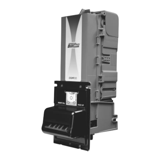
SECTION 1: GENERAL INFORMATION Dimensions and Specifications Figure 1 Power Requirements 22 to 45 VDC 0.2 Amp average standby 2.5 Amp average operating Operating Temperature 0°F to 150°F -18°C to 65°C Storage Temperature -22°F to 165°F -30°C to 74°C Relative Humidity 5% to 95% non-condensing Physical Weight in Shipping Carton 4 pounds... -
Page 6: Section 2: Installation
1. Remove the vending machine's power. through all possible configuration options and select 2. Install the BillPro Series bill acceptor into the mounting the required configuration. The illuminated inlet hole of the vending machine using the appropriate provides feedback to the user during the configuration hardware (NOT INCLUDED). -
Page 7: Section 3: Operation
SECTION 3: OPERATION BILL RECOGNITION Left and Right Alignment Sensors The left and right alignment sensors send information to When a bill is inserted into the bill acceptor and it blocks the microprocessor to insure that the bill is the right width the left and right alignment sensors as well as the center and that it is being fed in correctly. -
Page 8: Component Explanation Drawing
SECTION 3: OPERATION Figure 3 Component Explanation Bill Box Lid Intermediate Frame Stacker Home Pusher Encoder Sensor Plate Pushplate Assy Flex Stack Bill Box Lower Center Drive Housing Belt Left-Right Optic Center Optic Left Alignment Sensor Anti-Pullback Chassis Belt Lever Right Rollers Alignment Sensor... -
Page 9: Interconnect Drawing (Bp)
SECTION 3: OPERATION Interconnection Figure 4... -
Page 10: Section 4: Maintenance
SECTION 4: MAINTENANCE DISASSEMBLING THE BILLPRO Figure 5 Removing the Bill Box (see Figure 5) Bill Box Tab Push the bill box tab forward while sliding the bill box up. Bill Box Figure 6 Removing the Lower Housing (see Figure 6) - Page 11 SECTION 4: MAINTENANCE Removing the Intermediate Frame Figure 7 Intermediate Frame (see Figure 7) Using a small straight tip screwdriver, free the ten Main Frame locking tabs which secure the intermediate frame to the main frame and remove the intermediate frame. Lower Lower Upper...
- Page 12 SECTION 4: MAINTENANCE Removing the Upper Sensor Board from Figure 9 the Chassis (see Figure 9) Remove upper PCB cover by unsnapping from front. Using a small Phillips screwdriver, remove two screws securing the upper PCB to the upper enclosure. Unplug the chassis harness from the upper sensor board.
-
Page 13: Disassembling The Chassis
SECTION 4: MAINTENANCE DISASSEMBLING THE CHASSIS Figure 11 Removing the Pusher Plate from the Chassis (see Figure 11) Screwdriver Remove the pusher plate from the stacker gear box Chassis assembly by slightly spreading the pusher plate until it clears the stacker motor cam assembly. Pull the pusher plate straight out until the locking tabs of the stacker slides catch the chassis. - Page 14 SECTION 4: MAINTENANCE Removing the Chassis Belts and Pulleys Figure 13 (see Figure 13) Transport Motor Compress the belt tensioning spring by pressing down on Assembly the transport motor and gear case assembly and remove the belts. Slide the pulleys off the lower shafts to prevent them from falling off.
-
Page 15: Disassembling The Lower Housing
SECTION 4: MAINTENANCE DISASSEMBLING THE LOWER PCB Cover Figure 15 HOUSING Outer Tabs Removing the Printed Circuit Board (see Figure 15) Using a small straight screwdriver, pry up at the two outer tabs on the lower PCB cover. Pivot the front of the cover up and then slide forward. - Page 16 SECTION 4: MAINTENANCE Removing the Lower Housing Figure 17 Anti-Pullback Lever and Spring (see Figure 17) Using a small drift or Phillips screwdriver, depress the locking tab in the small hole in top of the lower housing. At the same time, insert a small standard blade screw- driver into the center slot and push the anti-pullback assembly back out of the retaining tabs.
-
Page 17: Billpro Cleaning Maintenance Procedure
BillPro bill acceptor. The BillPro should be cleaned every 20,000 bills or every two years (or as needed, depending on the environmental Procedure conditions of the location). Dust can be removed with a Remove power from the bill acceptor. -
Page 18: Section 5: Troubleshooting
If a bill acceptor cannot be repaired by following this guide, return the unit to the nearest Coinco Service Center for repair along with a complete description of the problem you are having with the bill acceptor. -
Page 19: Section 6: Parts List
Security Bottler Mask Used on BP2BXM and BP4BXM 925511 Snack Mask 345-6R6 Screw 920807-6 Main Frame 920065-2 Mounting Frame, Bottler 921492 Mounting Frame, Snack 925290 Grounding Spring 438-6 Hexnut & Lock Washer 925402 BillPro Front Label Bottler 925505 BillPro Front Label Snack... - Page 20 SECTION 6: PARTS LIST LOWER HOUSING ASSEMBLY...
-
Page 21: Lower Housing Assembly
SECTION 6: PARTS LIST ITEM NO. PART NO. DESCRIPTION QTY. NOTES 925285 Lower Cover 408500 Logic PCB Assy. 925347 Anti-Pullback Light Pipe Shroud 925284 Lower Enclosure 923102 Spring 920889 Anti-Pullback Lever Spring 920819-1 Anti-Pullback Lever Mount 925343 Anti-Pullback Lever 408542 Anti-Pullback Lever &... -
Page 22: Chassis Assembly
SECTION 6: PARTS LIST CHASSIS ASSEMBLY... - Page 23 Stacker/Encoder Housing & Board Assy. 408054 Upper Transport Pulley & Hub Assy. 407254-5 Transport Motor Gearbox Assy Includes #4 920000-3 Encoder Wheel 408526 Stacker Pushplate Assy. BillPro Includes #6 & #7 920836 Stacker Cap 920833-1 Stacker Slide 925202 Belt Tension Spring 407253-8 Stacker Motor Gearbox Assy.
-
Page 24: Intermediate Frame Assembly
SECTION 6: PARTS LIST INTERMEDIATE FRAME Flex Stacker ASSEMBLY (408522) (408261) - Page 26 COIN ACCEPTORS, INC. 300 Hunter Avenue St. Louis, MO 63124-2013 Coinco Publication No. 925495 Rev.1 (314) 725-0100 or (800) 325-2646 03/2004 Printed in the U.S.A.
Need help?
Do you have a question about the BillPro and is the answer not in the manual?
Questions and answers