Table of Contents
Advertisement
Advertisement
Table of Contents
Troubleshooting

Summary of Contents for C-THERM TCi
- Page 1 C-Therm TCi Operator Manual TH130041 Rev. H...
-
Page 3: Table Of Contents
C-Therm TCi System Setup ..................4 1.3.1 Checking the items and their condition..............4 1.3.2 Checking grounded cable ..................4 1.3.3 Making connections....................4 1.3.4 Starting up the C-Therm TCi system ...............4 C-Therm TCi Software Use ....................5 Menu Items ........................5 Table Use........................8 2.2.1 Menus ........................9 2.2.2 Buttons.........................10 2.2.3... - Page 4 Equipment ......................105 9.7.5 Calibration ......................106 9.7.6 Additional Notes – Heat Equation ...............107 Appendices ..........................110 Appendix A: System Components and Accessories............. 110 Appendix B: C-Therm TCi Controller Specifications ............. 111 C-Therm TCi Sensor Specifications.................112 C-Therm TCi Standard Computer Specifications ............. 113...
- Page 5 TCi Operator Manual Appendix C: Materials of Construction and Chemical Resistance Data ........ 114 Appendix D: Reference Material Standard Values ............... 118 Appendix E: Permission Default Values................119 Appendix F: CE Certification....................121 Appendix G: Units and Conversions ..................122 Appendix H: Contact Agent MSDS – Glycol.................124...
- Page 6 TCi Operator Manual...
-
Page 7: Introduction
This operating manual provides in-depth guidance to users in leveraging the C-Therm TCi for its intended use. It is very important that users invest the time in reviewing the information provided within this document for the safe and effective application of this advanced technology. -
Page 8: A Note On Instrument Limitations
TCi Operator Manual A note on instrument limitations It should be noted that in applying an instrument such as the C-Therm TCi in testing a wide variety of materials, material types and temperature ranges, careful consideration should be given to the limitations in performance and/or use of this system under certain conditions. In many cases, the C-Therm TCi can replace as many as four (4) traditional thermal conductivity instruments that covered the same claimed range of testing. -
Page 9: C-Therm Tci Manual Intent
Material Group is necessary for accurate results. Material groupings can be further optimized for the specific needs of a user - either by C-Therm on a contract basis, or through additional training and software module extension for user calibration capabilities. -
Page 10: C-Therm Tci System Setup
C-Therm TCi System Setup 1.3.1 Checking the items and their condition The standard C-Therm TCi system will arrive in a Pelican Case. Inspect the case for shipping damage and report this immediately to your shipping department to address with the courier company. -
Page 11: Therm Tci Software Use
Menu Items The C-Therm TCi software main menus are located across the top of the main window. The File menu contains: New Test – Clicking this option begins a new test. It has the same effect as clicking the New Test button on the toolbar. - Page 12 Contact Agents - Contact agents ensure good contact between the sensor surface and solid samples. Instruments – An instrument is a TCi controller. The instrument record lists the controller serial number and the instrument family. Testing Test Methods –...
- Page 13 TCi Operator Manual The Reports Menu lists the different reports that can be generated in the C-Therm TCi software Audit trail Report – The audit trail report lists all activities fitting entered parameters that occur within the software, such as creating records, performing tests, importing and exporting.
-
Page 14: Table Use
Index – The index lists individual topics and keywords in alphabetical order. Search – The user enters keywords and a list of topics fitting the entered keywords is displayed. About – The about window displays version information about the C-Therm TCi software. Table Use Tables can be opened by clicking a button from the Setup window or by selecting an option from the Manage menu. -
Page 15: Menus
TCi Operator Manual The table has File and Audit Trail menus at the top, nine buttons beneath, and fields to enter keywords for searching. The area for table entries takes up the remaining space. The table is opened with no entries. To display all entries, click the search button. Keywords can be entered to refine the search. -
Page 16: Buttons
TCi Operator Manual Edit – Select a record and click the Edit option. The information contained in the record can be edited and saved. Add – Clicking the Add option displays an empty record that can be filled and saved. -
Page 17: Using The Parameter Fields To Search
TCi Operator Manual Close – Click this button to close the current table. 2.2.3 Table Options When any row of the table is right-clicked, four options are displayed. Copy to Clipboard – Clicking this option copies the current table to the clipboard. The table can then be pasted into a spreadsheet program. -
Page 18: Create A Record
TCi Operator Manual 2.3.1 Create a Record Each individual record type has a different creation process. Record creation is detailed in the Record chapter. 2.3.2 View a Record Step 1 – Open the record’s table. Select the record type from the Manage menu or click the record type in the Setup window. For example, to open a material click Material in the Setup window. -
Page 19: Edit A Record
TCi Operator Manual Step 4 – Select the desired record. Step 5 – Click the View button. 2.3.3 Edit a Record Step 1 – Open the record’s table. Select the record type from the Manage menu or click the record type in the Setup window. For example, to open a material click Material in the Setup window. -
Page 20: Recover A Record
TCi Operator Manual Step 4 – Select the desired record. Step 5 – Click the Delete button. 2.3.5 Recover a Record Step 1 – Open the record’s table. Select the record type from the Manage menu or click the record type in the Setup window. For example, to open a material click Material in the Setup window. - Page 21 TCi Operator Manual Change the print options by clicking Print Setup from the File menu. Click the Printer button to select a printer (if multiple are available) or to see the printer's status. Step 3 – Click the OK button.
-
Page 22: Records
Projects are not necessary to run tests. A default project is included in the C-Therm TCi software and is all that is required to perform a test. As more data is collected, the project can be used to filter data. -
Page 23: Material
A default material name is included in the C-Therm TCi software and is all that is required to perform a test. As more data is collected, the material name can be used to filter data. -
Page 24: Material Lot
TCi Operator Manual If multiple grades of the material are in use, indicate the grade in the material name. Do not specify the material lot as this is covered separately. Step 4 – Select a material group. If no group is selected, the material group is set to the default material group by the software. - Page 25 TCi Operator Manual the records discussed previously, the test method is required and must be selected before a test with any parameters other than the default can be performed. Step 1 – Open the test method table. Step 2 – Click the Add button.
-
Page 26: Contact Agents
Step 5 – Enter the correction factor equation B value. Step 6 – Click the Save button. Notes Notes can be attached to any other record in the C-Therm TCi software. They are accessible through the Notes button on most records. Step 1 - Open a record. -
Page 27: Calibration Materials
TCi Operator Manual Step 2 - Click the Notes button. The notes table is displayed. Step 3 - Click the Add button. Step 4 - Enter the note. The note can be up to 200 characters long. Step 5 - Click the Save button. -
Page 28: Calibration Material Groups
TCi Operator Manual Step 3 – Enter the calibration material name. Step 4 – Enter a description for the calibration material (optional). Step 5 – Click the Add button twice in the Cal Material Values frame. Step 6 – Select Effusivity for the first row. -
Page 29: Calibration Methods
TCi Operator Manual Step 3 – Enter the Cal Material Group name. Step 4 – Click the + button to add a calibration material to the group. Step 5 – Select a calibration material from the drop-down list. Step 6 – Repeat steps 4 and 5 as needed to enter all calibration materials. - Page 30 TCi Operator Manual Step 3 – Enter a Calibration Method Name. Step 4 – Select an Instrument Family. This may usually be left as ESP Family. Step 5 – Select the Calibration Material Group. Five calibration material groups come standard with the software: liquids and powders, foams, polymers, ceramics, and metals.
- Page 31 TCi Operator Manual There are three ranges to enter: temperature, thermal conductivity, and effusivity. These ranges limit the circumstances under which calibration results obtained with the calibration method can be used. For example, if the calibration results are used in a test and the thermal conductivity falls outside of the declared range, the cell containing that result will be orange.
-
Page 32: Testing
TCi Operator Manual 4 Testing In general, testing with the C-Therm TCi system is intended to be fast. It can directly measure thermal conductivity or effusivity. It can indirectly measure diffusivity, heat capacity, the R-Value, or depth of penetration. Material... - Page 33 TCi Operator Manual Step 5 – Click the Next button. Step 6 - Select the test method to be used. A test method describes the parameters of a test: when to take measurements, what power level and timing parameters to use, and how many measurements to take. Select a test method that uses a calibration method with the calibration material group and power level appropriate to the test material.
- Page 34 TCi Operator Manual Step 8 – Select the Material Group. Step 9 – Select the Material to test. Note: Please select the material on the sensor. To create a new material, click the New Material button above the material frame.
- Page 35 TCi Operator Manual Step 12 – Select the sensors. Step 13 – Select the contact agent. See the table in section 4 for a guide to contact agents. Detailed background is located in section Step 14 – Select the Material Lot (optional).
- Page 36 TCi Operator Manual The values in the Test Results Table are explained in the following table. Value Meaning Effusivity The effusivity is calculated by comparing the sensor response to the (W√s/m factory calibration. k (W/mK) The thermal conductivity is calculated by comparing the sensor response to the factory calibration.
-
Page 37: Foam Testing
Handle the sample with gloves to prevent thermal contamination. Step 2 – Carefully place a weight on the sample. The 500 gram weight (supplied by C-Therm Technologies Ltd.) provides consistent pressure and keeps the sample in good contact with the sensor surface. -
Page 38: Solid Testing
TCi Operator Manual Solid Testing Solids include any non-foam solid materials such as ceramics, metals, wood, polymers, and glass. The power level depends on the nature of the solid. The power level for tests on low thermal conductivity materials such as polymers, ceramics, and wood should be 90. The power level for tests on high thermal conductivity materials such as metals should be 125. -
Page 39: Blotter Or Thin Sample Testing
TCi Operator Manual Note: Volumes of liquid as low as 1/4 tsp (1.24 mL) can also be tested with the Small Volume Test Kit Accessory. Contact your C-Therm representative for more information. Step 2 - Place the sensor into the beaker. - Page 40 TCi Operator Manual Step 7 – Resume the test. Step 8 – Stop the test after another 4 measurements. Step 9 – Right-click the 4 measurement. Step 10 – Select the Overlay Voltage Chart option. Step 11 – Right-click the 8 measurement.
-
Page 41: Indirect Property Calculations
Example of a failing blotter test: Indirect Property Calculations Several properties can be determined indirectly from test results using the C-Therm TCi software. The derived properties are displayed in the results grid of a test. Below are the theoretical base calculations that are used for the software calculations. -
Page 42: Altering The Test Method During The Test
TCi Operator Manual Where α is the diffusivity, and t is the test time from the thermal conductivity calibration. The thermal diffusivity, heat capacity, or density must be entered for this value to be calculated. Altering the Test Method during the Test The test method can be altered during the test by clicking the Alter Test Method button at the top of the test window. -
Page 43: Contact Agents
4.11 Contact Agents The C-Therm TCi sensor surface is made of a solid material. It can measure liquids, powders, and pastes by direct contact with these materials. However, when it comes in contact with solids, there is always a contact resistance. Using a contact agent minimizes the contact resistance. -
Page 44: Testing With Wakefield 120 Thermal Grease
(water or glycol) as they may be absorbed by the sample material and affect the measurement. C-Therm recommends Wakefield thermal grease as a replacement contact agent. Wakefield Type 120 Thermal Joint Compound is supplied with the TCi system. - Page 45 Use the general procedure and select the Wakefield Type 120 as the contact agent. Note: The contact agent correction factors must be entered into the TCi database for temperatures other than ambient (20-25°C). Values for all other temperatures are above.
-
Page 46: Chemical Testing With Rtv Tabs
Step 12 – Clean the beakers. Step 13 – Evaluate the results. A chemical is to be designated as safe to be used with the TCi sensors if it has no effect on the RTV test tab (effect A as noted below). - Page 47 TCi Operator Manual Chemical Temp 1 hour 2 hours 3 Hours 4 hours 24 Hours Safe/Not Safe Legend of Effects: A – No Effect B – Some Warping, puffiness C – Some Pitting or discoloration D – Severe Damage, loss of flexibility...
-
Page 48: Data Analysis Techniques And Practices
TCi Operator Manual 5 Data Analysis techniques and practices Opening a Test An opened test appears the same as a test being performed with the exception of the test control button field, which is not displayed. Step 1 - Click the Open Test button on the toolbar/in the main menu. -
Page 49: Reports
TCi Operator Manual Step 3 – Click the Test Details button at the top of the window. View the details of the test method, instrument, project, and material by clicking the … button beside the appropriate field. Step 4 – Edit any details with a white or blue background or Material by clicking the ? button. -
Page 50: Exporting And Importing
TCi Operator Manual Exporting and Importing Records can be transferred between databases and computers by exporting and importing XML files. Test results, calibration methods, calibration materials, calibration results, and test methods can be exported and imported. All attendant records with the exception of user calibration results (when exporting test methods or test results) and notes are exported and imported with the test results, user calibrations, or test methods. - Page 51 TCi Operator Manual Step 2 – Enter keywords in the parameter fields. Step 3 – Click the Search button or press the Enter key. Step 4 – Select the records to export from the displayed list. Step 5 – Click the Next button.
-
Page 52: Import
TCi Operator Manual Step 6 – Select a destination for the export file. Step 7 – Click the Export button. 5.6.2 Import Step 1 – Select the type of record to import from the Tools menu. Step 2 – Select the file to import. - Page 53 TCi Operator Manual Step 3 – Click the Import button.
-
Page 54: User Calibration
TCi Operator Manual 6 User Calibration The User Calibration features supplement the factory calibrations. They allow the user the flexibility of being able to modify calibration ranges, timing options, and power levels to suit their specific requirements. User Calibrations can be exported and imported between databases in the same manner as calibration methods, test methods, and test results. - Page 55 TCi Operator Manual Step 3 – Enter a calibration method name. Ensure that the name is descriptive of the type of material it will be used for. Step 4 – Click the Manage User Cal Materials button (if required). Steps 4 to 11 may be omitted if all calibration materials exist in the database.
- Page 56 TCi Operator Manual Step 6 – Enter the new calibration material name. Step 7 – Enter the new calibration material description. Step 8 – Enter material properties. At least one temperature and thermal conductivity point must be added to allow the material to be included in user calibrations.
- Page 57 TCi Operator Manual The start time is the delay after current is applied to the sensor chip before the data is used for calibrations. This time allows the heat wave to penetrate the glass coating on the sensor chip and the contact agent between the sensor and the sample.
- Page 58 TCi Operator Manual The count is the number of measurements to be taken on each calibration material. Step 22 – Select the first calibration material. Step 23 – Place the calibration material. Solid non-porous materials: Place three drops of contact agent on the sensor surface. Place the calibration material on the sensor.
- Page 59 Holding the mouse over the Bar beside the results will display the Good, Average, or Poor rating. The m* value is generated by an iterative algorithm patented by C-Therm to ensure a more linear thermal conductivity calibration. Larger m* values indicate that the samples required more adjustment to form a straight line.
- Page 60 TCi Operator Manual Step 30 – Click the Next button. Step 31- Click the Save Result button. Step 32 – Perform a reference material test to test the user calibration.
-
Page 61: Opening Or Continuing A User Calibration In The Wizard
TCi Operator Manual If the calibration does not pass or does not perform as desired, open the calibration wizard again and take more measurements or create a new calibration method with different parameters. Opening or Continuing a User Calibration in the Wizard A user calibration may be reopened to view graphs or take more calibration material measurements. - Page 62 TCi Operator Manual Step 3 – Select a calibration method from the list and click the next button. Step 4 – Click the Manage User Cal Materials button to add or edit calibration materials. Step 5 – Click the Next button.
- Page 63 TCi Operator Manual Step 6 – Click the Retrieve existing samples button (if required). If using an established user calibration to calibrate a new sensor, do not retrieve existing samples. If adding more samples to a previously started calibration, retrieve samples before taking new measurements.
-
Page 64: User Calibration Overview
TCi Operator Manual Step 9 – Click the Select button. Step 10 – Continue testing as for a new user calibration. Continue from step 22 of the new user cal procedure in section 6.1. User Calibration Overview Users comfortable with the new User Cal Wizard are not required to use this form of user calibration. -
Page 65: Create Calibration Materials
TCi Operator Manual Step 3 - Create the calibration method. The calibration method contains the timing parameters, power level, and calibration material group to be used for the calibration. Building the Calibration More information on calibration building can be found in the Acquire Calibration Data and Compute Results sections. -
Page 66: Create Calibration Method
TCi Operator Manual Step 5 – Click the Add Row button once for each material in the group. Step 6 – Set each row to one of the materials. Step 7 – Click the Save button. Create Calibration Method Step 1 – Open the Calibration Method table. - Page 67 TCi Operator Manual Step 3 – Leave New Calibration Test selected and click the Next button. Step 4 – Select the Instrument. Step 5 – Select the Calibration Method. Step 6 – Click the Next button. Step 7 – Select a calibration material.
-
Page 68: Compute Results
TCi Operator Manual Step 8 – Place the calibration material on the sensor and place the weight carefully on top. Use three drops of water contact agent for non-foam, non-porous solids. Step 9 – Click the Get Samples button. Step 10 – Once complete, select the next calibration material. - Page 69 TCi Operator Manual Step 4 – Select the Calibration Test. Step 5 – Click the Next button. Step 6 – Select the sensor (if required). Step 7 – Click the Compute button.
- Page 70 TCi Operator Manual Step 8 – Confirm that the R2 value is at least 0.995. Step 9 – If the results are good, click the Valid checkbox. Step 10 – Click the Next button. Step 11 – Click the Save CalResults button.
-
Page 71: Software Setup And Maintenance
7 Software Setup and Maintenance Setup If multiple C-Therm TCi instruments are used within the same company, a network database is advised instead of using a local database. SQL Server or Oracle and a TCP/IP connection over a fast Ethernet network are required for multiple systems to be connected. - Page 72 TCi Operator Manual Step 5 – Click the close button. Express Configuration Step 6 – Click the Next button.
- Page 73 TCi Operator Manual Step 7 – Change the COM port if required. Step 8 – Click the Finish button. Note: Continue to step 20 following the Custom Configuration section. Custom Configuration (to add or modify the database connection). Step 6 – Select the custom configuration option.
- Page 74 TCi Operator Manual Step 10 – Enter a new database name and ID. Step 11 – Click the New button. Step 12 – Enter a Database name or select a database to overwrite. Step 13 – Click the Open button.
- Page 75 Step 17 – Select all COM ports. Step 18 – Change the default User ID for login (optional). Step 19 – Click the Finish button. All Installations Step 20 – Open the TCi Software. Step 21 – Select Import from the Tools main menu.
- Page 76 Step 22 – Select Calibration Materials from the Import sub-menu. Step 23 – Click the Browse button. Step 24 – Select the Cal Bins 2011.xml file from the TCi Installation CD. Step 25 – Click the Open button. Step 26 – Click the Next button.
- Page 77 Step 27 – Click the Import button. Step 28 – Select Authorization from the Tools main menu. Step 29 – Click the Open File button. Step 30 – Select the Authorization TH89-05-00XXX [Module].xml file from the TCi Installation CD. Step 31 – Click the Open button.
-
Page 78: System Policies
Step 33 – Click the OK button. Install the USB to Serial Cable Drivers Step 34 – Open the Third Party folder on the TCi software CD. Step 35 – Open the USB_Serial_Prolific folder. Step 36 – Double-click the Setup.exe program. - Page 79 TCi Operator Manual Click the System Policies option on the Security menu. Step 2 – Set the number of failed login attempts. If a user enters the wrong password more than the set number of times, their account is locked and they cannot login.
-
Page 80: Manage Users And User Groups
TCi Operator Manual Step 8 – Set the database access. There are three options available for database user login as shown above. In the first, a single database is used for all users. In the second, users are connected to different databases depending on the first group listed in their profile. -
Page 81: Users
Step 6 – Click the OK button. 7.3.2 Users Every user has a profile or record within the C-Therm TCi software. The profile has a unique login ID that allows the user’s actions within the system to be limited and tracked. Activities are limited by the permissions the user has, as set in the user’s profile. - Page 82 TCi Operator Manual Step 3 – Enter the user’s name. Step 4 – Enter the user’s ID. Every user ID must be unique. Even if a user profile has been deleted, since no records can be permanently deleted, the user ID still cannot be re-used.
-
Page 83: Groups
User groups allow administrators to quickly set permissions for large numbers of users who perform the same actions within the C-Therm TCi software. Users added to a group have the permissions of that group. User groups can be edited, copied, deleted, and recovered in the same manner as other records. - Page 84 TCi Operator Manual The Technician group is for users who perform tests, run diagnostics, and generate reports. Step 1 – Open the user group table. Step 2 – Click the Add button. Step 3 – Enter the group name. Step 4 – Select users for the group and click the > button.
-
Page 85: Reactivating A Locked Account
TCi Operator Manual Any permission with a value of Default can be overruled by permission values set in other groups to which the user belongs. If there are actions the users of the group must or must not be able to perform, set their values to Permit or Deny. - Page 86 TCi Operator Manual Step 1 – Click the Change Password option in the file main menu. Step 2 – Enter the current password. Step 3 – Enter the new password. Step 4 – Confirm the new password by entering it again.
-
Page 87: System Calibration And Maintenance
Note: Factory calibrations are loaded on the sensor and do not require import. They do, however, need to be unlocked in the software. An authorization XML file is provided on the C-Therm TCi Software CD and will unlock the modules purchased. The file can also be obtained by emailing support@ctherm.com. -
Page 88: Diagnostics
TCi Operator Manual Step 5 – Click the Add Keys button. Diagnostics Diagnostics confirm the functionality of the instrument, test the sensor calibration, and aid troubleshooting. The diagnostics window displays the instrument’s status, calibration data, and board inventory. 8.2.1 Reference Material Test Use the reference material test to confirm that the sensor’s calibrations are still valid. - Page 89 TCi Operator Manual *Note: Due to variability between batches, there are multiple calibration material records for LAF 6720 and Phosphor Bronze. When performing a test, select the record matching the label on the reference sample. All reference material values are located in Appendix D.
- Page 90 TCi Operator Manual Step 4 - Select an Instrument. Step 5 – Select the calibration method. The reference material to be used is determined by the calibration material group specified in the calibration method selected. Step 6 – Select the sensor(s) to be used.
- Page 91 The result is displayed. All results should be within 5% of the predicted value (displayed under the reference material name). If the result is in a red cell, the diagnostic has failed. If the diagnostics fail, a new calibration may need to be performed. Contact C-Therm Technologies Ltd. for troubleshooting.
-
Page 92: System Checks
Calibration results for the selected calibration method are displayed in the top table. All calibration results on the sensor ID chip are listed in the bottom table. If a calibration is labeled as LOCKED, it must be opened with an authorization key from C-Therm Technologies. -
Page 93: Cleaning Procedure
Warning: Prior to cleaning - shut down the control unit and disconnect the power plug at the outlet. The C-Therm TCi system is comprised of a controller, sensor(s) and cables. Different parts of the system tolerate different cleaning materials and methods. Please follow these guidelines to ensure proper operation of the C-Therm TCi system. -
Page 94: Troubleshooting
Troubleshooting 8.4.1 General Information required If problems are encountered in the C-Therm TCi software, please send a copy of the database, log files, detailed explanation of the problem, the expected result, and steps to reproduce the problem to C-Therm customer technical support at support@ctherm.com. The details should be in a doc file with a screen capture of the error message and a screen capture of the Help About dialog. -
Page 95: Troubleshooting List
If a "No instrument found" error is displayed, check to make sure that the power cable is connected, the power is on, the USB-Serial cable is connected to both the C-Therm TCi Controller and laptop, and the sensors are attached to the controller. Click the Refresh button to re-try. - Page 96 I cannot use any calibrations loaded on my sensor. Click Authorization from the Tools menu. If there are no entries for the C-Therm TCi Controller connected to the laptop, the calibrations will not be available.
- Page 97 TCi Operator Manual Insert the C-Therm TCi Software CD into the laptop and press the Open File button. Locate the Authorization TH89-05-XXXXX.xml file on the CD and click the Add Keys button. The calibrations will be available for use. The cooling time in my test changed and is not what is set in the calibration method.
-
Page 98: Theory Of Operation
TCi Operator Manual 9 Theory of Operation TCi Calibrations 9.1.1 Sensor temperature calibration This section explains the relationship between the sensor’s change in temperature, , its resistance and its voltage drop , and how to calculate from TCR (temperature coefficient of resistivity) calibration parameters. -
Page 99: Basic Multi-Point Effusivity Calibration
TCi Operator Manual The slope A is equal to: Where: TCR = Temperature Coefficient of Resistivity, assumed to be constant over the measured temperature range. Notes: 1. The slope depends on sensor resistance in general, and on R in particular. - Page 100 TCi Operator Manual equilibrium after contact between them has been established. The solution of equation (6) follows these expressions: X<0 X>0 ierfc ierfc Where: ΔT = change in sensor surface temperature (ºC)
- Page 101 TCi Operator Manual If no contact resistance exists at the interface, at all points with . For equations (7) and (8) are reduced to: 1284 5642 In the previous section we saw the connection between sensor temperature and resistance. The resistance change of the sensor is: ...
- Page 102 TCi Operator Manual (15) 1284 If e is 0, i.e. sensor response is measured in vacuum, then: vacuum (16) 1284 The figure (e /IAG) is a sensor/system figure of merit, and depends only on sensor characteristics and supplied power, and may be used for calibration.
- Page 103 TCi Operator Manual C is the 1/m value for vacuum. (20) , sensor effusivity can be calculated from (20). In practice, for high effusivity (high k) materials equation (13) is inaccurate, because the heat flows also laterally and the one-dimensional heat flow assumption is no longer satisfied.
-
Page 104: Material Groups And Power Levels
The wide range of effusivity and k requires grouping of materials with similar behavior and effusivity/k range, and operation of the TCi sensor at different power levels. Each group of materials has its own calibration curve, which is of course affected by the power level. -
Page 105: Contact Agent
4. All groups use start time 0.3s and stop time 0.8s. Contact agent The TCi sensor has a solid and hard surface. When measuring solids, there will always be some contact resistance, which may significantly affect the results. The quality of heat transfer depends on many parameters such as type of material, surface quality, etc. -
Page 106: Thermal Conductivity (K) Calibration
TCi Operator Manual For example, CF=a*(1/m)+b. If a=1.1 and b=0.3, and the measured 1/m=100, then the corrected 1/m to be used for the calculation of effusivity and k would be 110.3 (1/m is automatically corrected by software). Presently, 2 CAs other than water are used, glycol for low temperature (down to -50C) and Wakefield 120 thermal grease for high temperatures, extended testing, and porous or absorbent materials. -
Page 107: Limitations For K Measurements
TCi Operator Manual The algorithm to calibrate and calculate k is the m*, which is outlined in US Patent 6,676,287 B1. It uses an iterative process to calibrate the sensor against measured materials with known thermal conductivity. The calibration process generates a value called m*, such that: A typical k calibration has this form: ... -
Page 108: Temperature Considerations In Effusivity Calibration
Note: C(T) and its 3 coefficients are different at different power levels. This entails that C(T) has to be measured at all power levels used. The figure below shows this relationship of one of the TCi sensors measured between -30C and +200C in vacuum. -
Page 109: Temperature Considerations In Conductivity Calibration
TCi Operator Manual Conclusions: 1. The parameters M and M of the effusivity calibration of the sensor over temperature range are constant as long as the current supplied to the sensor may be corrected to compensate for change in its resistance, such that remains constant. -
Page 110: Error Analysis
TCi Operator Manual in V/ s (31) Is the corrected slope for temperature T. =150 s/V and 1/m =160 s/V, and the k For example, suppose a material under test has 1/m calibration has these parameters: Slope=100 smK/WV, Intercept=90 s/V and m =0.0015 V/ ... -
Page 111: Material
TCi Operator Manual Errors in effusivity and conductivity measurements have four significant sources: variations in the tested material, quality of contact between sensor and tested material, errors from equipment and errors from calibration (offset only). 9.7.2 Material Variations in tested material will change the heat transfer characteristics. A good example is humidity content in powders. -
Page 112: Calibration
TCi sensor. The overall accuracy of the TCi is estimated at 5% between 0C and 50C, and up to 10% above or below that temperature range. The variation is typically 1-2% (%RSD calculated from at least 10 consecutive samples, at 0C to 50C). -
Page 113: Additional Notes - Heat Equation
TCi Operator Manual (35) And therefore: (36) The relative variance in 1/m is the same as the relative variance in m. From (17) we can calculate the variance in as (C is assumed constant for the set of measurements): ... - Page 114 TCi Operator Manual This equation describes the dynamics of temperature change and heat flow in a medium in one dimension (i.e. assume semi-infinite plane), with a source of heat G’ per unit volume supplied at the surface. The left side of the equation describes change of temperature in the medium versus time.
- Page 115 TCi Operator Manual The TCi case is more complicated than that, because the sensor-material system is in transient, not steady state. This is the reason we need to use equations (7), (8) and (9). If we write equation (6) in this form ...
-
Page 116: Appendices
C-Therm TCi. Special application developments – C-Therm’ experience can be used to create new test methods for new materials or processes. Testing migration services – C-Therm can provide consulting to migrate off-line testing to on- line processes, including on-line process control... -
Page 117: Appendix B: C-Therm Tci Controller Specifications
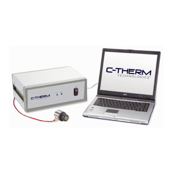
Appendix B: C-Therm TCi Controller Specifications Overview: The TCi is a state of the art thermal property characterization instrument based on the modified plane source technique. The TCi sensor is engineered for testing liquids, powders, pastes and solid materials. The system enables testing of a wide range of thermally conductive materials, ranging from foams to metals. -
Page 118: C-Therm Tci Sensor Specifications
C-Therm TCi Sensor Specifications Overview: The TCi is a state of the art thermal property characterization instrument based on the modified plane source technique. The TCi sensor is engineered for testing liquids, powders, pastes and solid materials. The system enables testing of a wide range of thermally conductive materials, ranging from foams to metals. Some of the points of difference that differentiate the TCi from other thermo-physical testing technologies are its rapid, non- destructive test method, greater ease-of-use and the overall sample flexibility it offers users. -
Page 119: C-Therm Tci Standard Computer Specifications
TCi Operator Manual C-Therm TCi Standard Computer Specifications (Note: Computer is specified subject to availability. C-Therm reserves the right to alter the make, model and configuration. May not be exactly as pictured. Laptop manufacturer’s warranty applies.) Feature Upgrades Available: Microsoft Office (RFQ) -
Page 120: Appendix C: Materials Of Construction And Chemical Resistance Data
The sensor is constructed from passivated 316 stainless steel, RTV (silicone), green glass, and silicon. If there is uncertainty as to the safety of using a chemical with the C-Therm TCi sensor, test the chemical with a tab of RTV before using it with the sensor. RTV is the weakest part of the sensor’s construction and will likely react most strongly to any chemical. - Page 121 Sodium Thiosulfate (hypo) Zinc Sulfate Propanol Soybean Oil The following chemicals are not safe to use with C-Therm TCi Sensors (Chemicals considered unsafe due to lack of information on one or more components are marked with *): Acetate Solvent Amyl Alcohol...
- Page 122 TCi Operator Manual Butylene Dimethyl Formamide Hydrochloric Acid 20% Butyric acid Dimethyl Terephthalate Hydrochloric Acid 37% Calcium Bisulfate Dioctyl Phthalate Hydrochloric Acid 100% Calcium Bisulfide Dioxane Hydrochloric Acid, Dry Gas* Calcium Sulfate* Diphenyl Hydrocyanic Acid Carbitol* Diphenyl Oxide Hydrocyanic Acid (Gas...
- Page 123 TCi Operator Manual Methyl Ethyl Ketone Potassium Hydroxide Tetrahydrofuran Methyl Ethyl Ketone (Caustic Potash) Tetralin Peroxide* Potassium Permanganate* Tidewater Oil* Methyl Isobutyl Ketone Propane (liquefied) Tin Salts Methyl Isopropyl Ketone Propyl Acetate Toluene (Toluol) Methyl Methacrylate Propylene Tomato Juice* Methylamine*...
-
Page 124: Appendix D: Reference Material Standard Values
TCi Operator Manual Appendix D: Reference Material Standard Values C-Therm Reference Thermal Effusivity (25°C) Thermal Conductivity (25°C) Material* W√s/m W/mK Distilled Water 1594.0 0.609 LAF 6720-A 161.4 0.082 LAF 6720-B 152.3 0.079 LAF 6720-C 171.06 0.086 Pyrex 1437.9 1.143 Pyroceram 2950.4... -
Page 125: Appendix E: Permission Default Values
TCi Operator Manual Appendix E: Permission Default Values Permission Sub Group Sub Group Default Value Group Test Methods Add Test Method Permit Edit Test Method Edit Draft Test Method Permit Edit Released Test Method Permit Delete Test Method Permit Recover Test Method... - Page 126 TCi Operator Manual Permission Sub Group Sub Group Default Value Group Recover Calibration Methods Deny Execute Calibration Methods Deny Perform One-Point Correction Permit Import Calibration Methods Deny Export Calibration Methods Permit Calibration Method Notes Add Calibration Method Permit Notes Edit Calibration Method...
-
Page 127: Appendix F: Ce Certification
TCi Operator Manual Appendix F: CE Certification DECLARATION OF CONFORMITY Supplier Name: Mathis Instruments Ltd Supplier Address: 21 Alison Blvd. Fredericton, New Brunswick Canada E3C 2N5 Declares under our sole responsibility that the following product Product Name: – Thermal Property Analyzer... -
Page 128: Appendix G: Units And Conversions
TCi Operator Manual Appendix G: Units and Conversions Basic symbols and dimensions: MKS (SI) Imperial Thermal Conductivity (cal/s C) (Btu/hr/ft/ F) (W/mK) F) or (Btu*in/hr/ft Thermal Diffusivity Cp (cal/g/ C) Heat Capacity (Btu/lb/ F) (J/kg/K) ... - Page 129 TCi Operator Manual Time: =0.01667 min =0.0002778 hr 1 W s cal s Effusivity: =2.388x10 / F =8.946x10 Btu/hr Length: = 100 cm = 3.2808 ft Calculation of Thermal Diffusivity: ...
-
Page 130: Appendix H: Contact Agent Msds - Glycol
TCi Operator Manual Appendix H: Contact Agent MSDS – Glycol This page left intentionally blank. - Page 131 Material Safety Data Sheet Dowtherm SR1 MSDS Section 1: Chemical Product and Company Identification Product Name: Dowtherm SR1 Contact Information: Sciencelab.com, Inc. Catalog Codes: SLD4267 14025 Smith Rd. Houston, Texas 77396 CAS#: Mixture. US Sales: 1-800-901-7247 RTECS: Not applicable. International Sales: 1-281-441-4400 TSCA: TSCA 8(b) inventory: Ethylene glycol;...
- Page 132 DEVELOPMENTAL TOXICITY: Not available. The substance may be toxic to kidneys, liver, central nervous system (CNS). Repeated or prolonged exposure to the substance can produce target organs damage. Repeated exposure to a highly toxic material may produce general deterioration of health by an accumulation in one or many human organs.
- Page 133 Products of Combustion: These products are carbon oxides (CO, CO2). Some metallic oxides. Fire Hazards in Presence of Various Substances: Slightly flammable to flammable in presence of open flames and sparks, of heat. Explosion Hazards in Presence of Various Substances: Non-explosive in presence of open flames and sparks, of shocks. Fire Fighting Media and Instructions: SMALL FIRE: Use DRY chemical powder.
- Page 134 Ethylene glycol STEL: 120 (mg/m3) [Australia] TWA: 100 (mg/m3) from ACGIH (TLV) [United States] CEIL: 125 (mg/m3) from OSHA (PEL) [United States] CEIL: 50 (ppm) from OSHA (PEL) [United States] TWA: 52 STEL: 104 (mg/m3) [United Kingdom (UK)] Inhalation TWA: 10 (mg/m3) [United Kingdom (UK)] SKINConsult local authorities for acceptable exposure limits. Section 9: Physical and Chemical Properties Physical state and appearance: Liquid.
- Page 135 Special Remarks on Reactivity: Hygroscopic. Absorbs moisture from the air. Avoid contamination with materials with hydroxyl compounds. Also incompatible with aliphatic amines, isocyanates, chlorosulfonic acid, and oleum (Ethylene glycol) Special Remarks on Corrosivity: Not available. Polymerization: Will not occur. Section 11: Toxicological Information Routes of Entry: Absorbed through skin.
- Page 136 Waste Disposal: Waste must be disposed of in accordance with federal, state and local environmental control regulations. Section 14: Transport Information DOT Classification: Not a DOT controlled material (United States). Identification: Not applicable. Special Provisions for Transport: Not applicable. Section 15: Other Regulatory Information Federal and State Regulations: California prop.
- Page 137 Flammability: 1 Reactivity: 0 Specific hazard: Protective Equipment: Gloves. Synthetic apron. Wear appropriate respirator when ventilation is inadequate. Safety glasses. Section 16: Other Information References: Not available. Other Special Considerations: Not available. Created: 10/10/2005 01:04 AM Last Updated: 11/06/2008 12:00 PM The information above is believed to be accurate and represents the best information currently available to us.
-
Page 138: Appendix I: Disclaimer
TCi Operator Manual Appendix I: Disclaimer While the information contained herein is believed to be reliable, the manufacturer makes no representations as to the reliability of the results the buyer or User will achieve. No statements or recommendations herein are to be construed as representations applicable to the particular application of the User or buyer or as inducements to infringe upon any relevant patent, now or hereafter in existence.
Need help?
Do you have a question about the TCi and is the answer not in the manual?
Questions and answers