Table of Contents
Advertisement
Advertisement
Table of Contents
Troubleshooting

Related Manuals for CPN MC3 ELITE

Summary of Contents for CPN MC3 ELITE
- Page 1 CPN MC3 ELITE ™ Moisture /Density Gauge OPERATING MANUAL www.InstroTek.com...
- Page 2 ‘This page may be removed from the manual to prevent the unauthorized access to the restricted menu functions of the InstroTek/CPN MC-3 Elite.’ Restricted Menu Function Access Code: 3548 Please note up to 2% of the mechanical components used in the gauge may...
- Page 3 This page may be removed from the manual to prevent the unauthorized access to the restricted menu functions of the InstroTek/CPN MC-3 Elite.
- Page 4 © 2018 InstroTek, Inc. MC-3 Elite Moisture/Density Nuclear Gauge Operation Manual Version 4...
-
Page 5: Table Of Contents
InstroTek 1. Table of Contents **************************************** 1. INTRODUCTION AND GAUGE COMPONENTS 2. GETTING STARTED 3. MENU FUNCTIONS 4. RADIATION THEORY 5. RADIATION SAFETY AND HEALTH PHYSICS 6. TRANSPORTATION 7. GAUGE THEORY 8. ROUTINE MAINTENANCE AND TROUBLESHOOTING 9. SPECIFICATIONS AND APPENDICES 10. - Page 6 InstroTek 1. Introduction Thank you for your purchase of the InstroTek/CPN Model MC-3 Elite. InstroTek/CPN has been a world leader in the development and implementation of nuclear gauges for over 45 years. InstroTek/CPN design and manufacture gauges used in variety of applications such as agriculture and irrigation control, coal density and moisture determination, moisture in pipe insulation and many more.
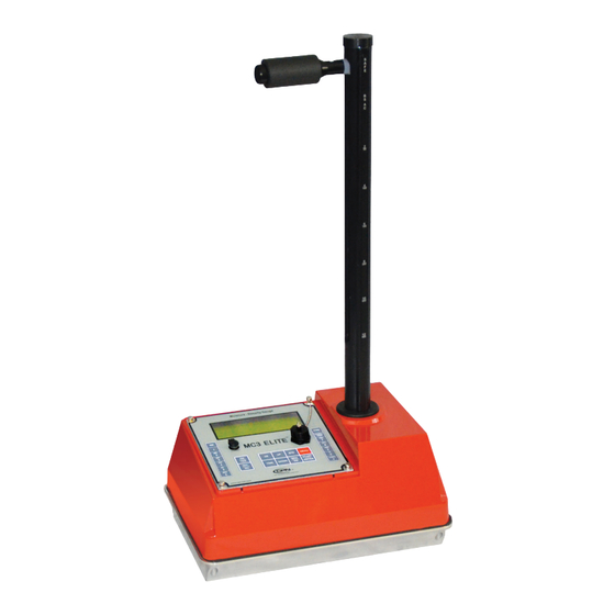
- Page 7 InstroTek Model MC-3 Elite and Standard Accessories Fig 1.1 MC-3 Elite Nuclear Gauge & Accessories Model MC-3 Elite 1. MC-3 Elite 2. Reference standard block 3. Scraper plate 4. Extraction tool 5. Drill rod 6. Type A shipping case 7. AC and DC charger, one each 8.
-
Page 8: Getting Started
InstroTek 2. Getting Started Before using this gauge, it is recommended that the user read this manual and understand the operation of the gauge. Operating your Model MC-3 Elite This chapter covers the basic operation of your gauge from powering on to taking a measurement. This manual should also be used for Smart-MC electronic upgrade to older MC1 DRP and MC3 gauges. - Page 9 InstroTek for the day. Charge the gauge overnight after the day of operation. During a charging session a “C” will appear in the upper right hand corner of the display. The gauge is designed with a SmartCharge chip that prevents the battery from over charging.
- Page 10 InstroTek Powering the Gauge On Use the ON/YES key to power the gauge on. When the gauge is powered on the CPN Elite will go through the following Self- Test screens: CPN Elite Version: #. ## Self-Test will take approximately 15 seconds and checks for proper operation of the keypad, density and moisture detectors, and the High Voltage.
- Page 11 InstroTek 4. High Voltage Failure - This indicates the high voltage module is not working properly. Important: It is suggested to always power the gauge on and allow the self-test to complete before leaving for a job site. Place the gauge on the reference standard block and check the results of the Self-Test and ensure there are no failures.
- Page 12 InstroTek Setting Units of Measurement The default for the gauge is lb. /ft3 (PCF). You may change the units to kg/m3 or g/cc by completing the following steps. Press the MENU button, the first screen will be: 1. Recall 2. Set Depth Up/DOWN FOR Next Select#, ESC Exit Scroll DOWN 5 screens...
- Page 13 InstroTek Press ESC to return to the gauge ready screen GAUGE READY COUNT TIME: 1 min. Depth: BS OFFSET: N 02/16/2013 12:07 PM Setting Test Time The gauge provides four different testing times: 15 seconds, 30 seconds, 1 minute, and 4 minutes. The gauge precision improves with increased test time.
- Page 14 InstroTek Measurement Depth The Elite gauge is designed and is equipped with an automatic non-contact magnetic depth indicator. The depth is automatically read as you lower the source into measure position and the appropriate constants are selected for calculation of density. The gauge can be placed into manual depth mode by disabling the Automatic depth mode from the MENU functions Taking a Daily Standard Count...
- Page 15 InstroTek Place the gauge on top of the standard block on a level surface; the keypad end of the gauge should be pushed against the metal butt plate. See Fig 2.1. Ensure the reference standard block is placed on a dense material, such as soil, asphalt, or concrete.
- Page 16 InstroTek Press the STD button on the front panel. The Standard Count will display with your previous standard count. DS= ### MS= ### Take New Std Count? Press YES or NO Press the ON/YES button to take a new count or press OFF/NO to cancel and go to the gauge ready display.
- Page 17 InstroTek DS is the density standard count and MS is the moisture standard count. Log these numbers into your Daily Standard Log Record (notebook), and then press the ON/YES button The gauge ready screen will appear and you are now ready to begin testing.
- Page 18 InstroTek Press 1 for setting soil target value PR (Proctor), and Press 2 for setting asphalt target value MAX (Max. Dens.). Press 3 for setting soil specific gravity (SG). Proctor PR: #### PCF Change value? Press YES or NO ESC to Exit Press the ON/YES button Enter Value For Proctor: ### PCF...
- Page 19 InstroTek Once the MA value is entered, the gauge ready screen will display. Soil SG Soil SG: #### PCF Change value? Press YES or NO ESC to Exit Press the ON/YES button Enter Value For Soil SG: ### PCF ENTER to Accept ESC to Exit Once the SG value is entered, the gauge ready screen will display.
- Page 20 InstroTek % PR can also be used to determine % Solids, if the “void-less density” of the material can be determined. ���� %�������� ������ ���������� = ������ ∗ [ �� − ( ) − ��] ���� Where: DD is the dry density in g/cm³, SG is the soil specific gravity provided by the user, and M is the moisture content in g/cm³.
- Page 21 InstroTek Site Preparation (soil, aggregates, and granular materials) Locate a test site away from other gauges and large objects that could influence the gauge results. These items include your truck, large concrete barriers or walls. If the test site is required to be near or close to walls, then refer to the special functions section, Offset and Trench Correction.
- Page 22 InstroTek Removal of the drill rod should be done in a manner that will not damage the hole. Using a twisting motion, pulling straight up on the drill rod might be the best way to extract the rod from the material. Care must be taken to preserve the integrity of the hole.
- Page 23 InstroTek Site Preparation (Asphalt) Locate a test site away from other gauges and large objects that could influence the gauge results. These items would include work trucks, large concrete barriers or walls. For coarse, open graded mixtures, fine fill material, such as Portland cement or fine sand, should be used to fill the voids, but taking care not to completely cover the surface of the asphalt.
-
Page 24: Taking Measurements
InstroTek Taking Measurements Lower the source rod to the desired depth by pulling the handle trigger back and pushing down on the handle. In positions of measurement, always ‘lock’ in to the position by allowing the trigger to engage the notch and then gently pushing the handle down to ‘seat’... - Page 25 InstroTek MM/DD/YYYY HH:MM AM DEPTH: BS Soil %AV: 10.0 PRESS UP/DOWN Where: M count = Moisture count D Count = Density count MCR = Moisture count ratio (M Count/MS) DCR = Density count ratio (D Count/DS) WD = Wet density %MA = Percent Compaction ((WD/Max Dens.) X 100) %Void = Percent air voids (100-%MA) Moisture = Moisture density in PCF, Kg/m3 or gcc depending on...
- Page 26 InstroTek Project Storage and Printing The Elite is equipped with data storage capability. Up to 10 Projects and 40 stations (readings) per project can be stored in the Elite. The stored data can be printed or transferred into a USB external drive located on the front panel. To access this feature and start a new project press the Project Print button: 1.
- Page 27 InstroTek Choose the desired starting station number and press YES. When Auto Store station is enabled, the station numbers will increment up sequentially from the starting station number. Enable Auto Store? Press YES or NO Choose YES to enable Auto Store to automatically store the project after each reading.
- Page 28 InstroTek Select which data you would like to print and press the corresponding number button. After you have selected the print option connect the printer to the gauge and press ENTER. To store to a USB device press, press the PROJECT PRINT Key and scroll down to the third page, option 5 5.
-
Page 29: Menu Functions
InstroTek 3. Menu Functions This chapter contains functions that may not be used every day. Features under Menu functions are important and will be used periodically for testing under special circumstances and special materials, performing diagnostics test and calibration functions. Pressing the MENU button on the front panel will access menu functions. - Page 30 InstroTek Select Language – Select either English or Spanish for the language. Set Units – Change units between lb./ft3, kg/m3, and g/cc. Standard Mode – Enable/Disable Average Standard Mode, Decay Mode and Chi2 Test Mode. Serial Number – Enter the serial number of the gauge. Date/Time –...
- Page 31 InstroTek Density - allows the addition or subtraction of a given quantity from the wet density (WD) readings measured by the gauge. This function can be used for correction of the gauge readings to other test methods, such as asphalt cores tested by water displacement method. Moisture - corrects the gauge moisture readings to oven or speedy dry moisture.
- Page 32 InstroTek dry or other laboratory drying methods. Use the following equation to calculate the correction and enter this value into the gauge when prompted by the software. Where %M (Gauge) is the gauge derived % Moisture (%M) value with K=0 (no moisture offset, factory calibration) and %M (True) is % Moisture determined by oven dry, speedy dry or other laboratory methods.
- Page 33 InstroTek The gauge is now in Trench Offset mode and ready to test. Note: If M Count is lower than MS, then there is no influence from the trench walls and trench offset is not necessary. Note: When trench offset is enabled a Y on the gauge ready screen will appear next to offset.
- Page 34 InstroTek Press the 4 button. Press YES to enable. To disable the feature repeat steps 1-4. The gauge will prompt to disable the backlight if it is on, pressing YES will disable the backlight. Note: Powering the gauge off will disable the backlight feature. Note: The backlight on the gauge causes a larger drain on the batteries than under normal use.
- Page 35 InstroTek High Voltage This function measures the high voltage on the board. This information is very important for trouble shooting the gauge enables technicians provide instructions on the status of the gauge. Please note, this measurement will not be available on Smart-MC with the old density and moisture modules.
- Page 36 InstroTek consists of performing five 240-second counts. To obtain a meaningful drift result, first take a Stat Test (please refer to the Stat Test) and wait 3-4 hours before starting a drift test. The average of the five drift moisture and density counts is compared against the average of the 20 one minute Stat test averages.
- Page 37 InstroTek 7. Stat Test A Stat Test may be performed to validate the normal operation of the gauge electronics. If two out of three stat tests fail the limits set in the gauge, contact your InstroTek representative. Passing limit on stat test results are R=0.25 to R=0.45. To perform a Stat Test: Press MENU.
- Page 38 InstroTek the gauge will prompt before every reading to manually enter a depth. Under this function, you can calibrate the depth sensors. In a rare case, they may fall out of calibration. Under Auto Depth function, select 1 to Enable/Disable the Auto Depth, or 2 for Calibration and follow the screen prompts.
- Page 39 12. Standard Mode Two different Standard Count Modes can be selected and used with the MC3 Elite, Average Mode and Decay Mode. The gauge default is the Average Mode. In the Average Mode, the percent change between the current standard count and the average of the last four standard counts taken by the gauge is displayed.
- Page 40 InstroTek 16. Special Calibration Special calibration provides the functionality to adjust the factory calibration in the field. Special calibration constant, B, can be derived by the gauge, or may be entered by using the equation given in this section for calculation of B. The gauge is calibrated at the factory to “average soil”, which is defined as material that is half way between pure granite and pure limestone.
- Page 41 InstroTek Where count ratio (Average count/std. count) determined by the gauge in the field, A and C are calibration constants for the depth of measurement used in the field and True density is density determined by a conventional method in the lab.
- Page 42 InstroTek Press YES to Enable Special Calibration and NO to go back to the gauge ready screen. Use Gauge to Derive B Value? Press YES or NO ESC to Exit Note: If special calibration has been used previously, the gauge will ask if the same calibration or previously stored data should be activated.
- Page 43 InstroTek Select the number of counts and desired depth. Place the gauge on the material at a desired location and press start to accumulate the first count. The gauge will prompt you to take counts until the selected number of counts has been completed.
- Page 44 InstroTek Once the density is entered, the gauge will calculate a B value and go into the Special Calibration mode. Record the B value. During measurements Special Calibrations will appear on the screen to indicate that the gauge is in special calibration mode.
- Page 45 InstroTek Value B may be entered directly into the gauge special calibration function if available from previous calculations. To enter the B value, press YES to activate the special calibration. B=###### Activate Special Calibration? Press YES or NO 17. Nomograph The Nomograph function allows for measurements of thin overlay density on asphalt or concrete.
- Page 46 InstroTek To use the Nomograph mode, place the source in the BS position. Obtain the top material thickness and the density of the material immediately under the thin overlay. The equation used for calculation of the overlay density is: Where DT is the overlay density, WD is the wet density measured by the gauge and K is the effect of the top layer on the density measurement.
- Page 47 InstroTek Enter Nomograph material thickness in inches or mm, depending on the unit already selected in the gauge. The range of thicknesses that can be used with this function is 1 to 3.5 inches (25 to 90 mm). Do not use this function for thickness outside this range, as the results will not be accurate.
- Page 48 InstroTek 18. Calibration Constants This function will require an access code. Contact your RSO or InstroTek to obtain an access code. Note: Only someone familiar with nuclear gauge setup and calibrations should perform these steps. Changing this information will result in erroneous readings. To enter calibration constants: Press MENU.
- Page 49 InstroTek Other Features of the Model MC-3 Elite Note: Only trained technicians should perform these functions. The Reset Button - This button will reset the operating program. If the program freezes or stops responding, then pressing this once will reboot the system. The gauge will not lose calibration constants, standard counts, or last measurement.
- Page 50 InstroTek Display Contrast J45 Connector Reset Button RS232 Connector Fig 3.1 Backside of the Front Panel circuit board...
-
Page 51: Radiation Theory
InstroTek 4. Radiation Theory This chapter covers information on basic atomic physics. It is important that the users have an understanding of this section in order to have a handle on applications and safety related issues. Elements/Atoms Elements are combinations of the three sub-atomic particles: Protons, Electrons and Neutrons. - Page 52 InstroTek The atom is not solid, it is mostly space. If the nucleus of hydrogen was the size of a marble and placed on the 50 yard line of a football stadium the electron would be the size a pinhead in the stands. Each element/atom has been assigned a one or two letter symbol that is an abbreviation of its name (generally Latin).
- Page 53 InstroTek Earth’s Crust Our task is to measure the density of soils. The elements in the periodic table we are concerned with are those in the earth’s crust. ELEMENT SYMBOL MASS % EARTH’S CRUST Oxygen 16.00 0.5000 49.9% Silicon 28.09 0.4984 26.0% Aluminum...
- Page 54 InstroTek Radioactivity Not all Isotopes are stable. Isotopes with atomic numbers greater than 92 are unstable. Americium used for moisture measurement in the nuclear gauge has an atomic number of 95. It is a by-product from neutron bombardment of Plutonium to produce weapons materials.
- Page 55 InstroTek Beta particles travel a few feet in air and are stopped by an inch of wood or a thin sheet of aluminum or plastic. In the nuclear gauge beta particles are stopped by the source containment Gamma rays travel hundreds of feet in air and can be shielded by thick lead or Fig 4.2 Penetrating Distances...
- Page 56 InstroTek Gamma radiation Gamma radiation is electromagnetic radiation that is released from nuclear reactions. X-rays, radio waves and light are some other examples of electromagnetic radiation. Gamma rays and visible light have no electrical charge or mass and travel at speed of light.
-
Page 57: Radiation Safety And Health Physics
InstroTek 5. Radiation Safety and Health Physics This chapter covers information on health physics and radiation safety concepts. Terms Roentgen The Roentgen is equivalent to 1 electrostatic unit of charge from interaction of gamma radiation in 0.001293 gram of air at 1 atmosphere pressure and is a unit of exposure. - Page 58 InstroTek Natural Radiation The best way understand the Rem is to know it relates to our everyday life. Annually humans are exposed 100 to 300 mRem (milliRem) per year from natural sources: Source Description Annual Dose Cosmic From the sun and other space sources and their reaction with the earth’s atmosphere.
- Page 59 InstroTek - Weapons testing fallout - 4 mRem - Medical X-rays - 9-210 mRem - Nuclear Moisture/ - 25 mRem/yr. Density Gauge Fig 5.1 Natural Radiation and Annual Dose Typical yearly totals are 123 mRem for someone living alone in a wood house in San Francisco, and whom does not;...
- Page 60 InstroTek radiation escaped, but it would be so heavy that it would not be a practical portable gauge. The three ways the operator has to reduce the dose: Time Minimize the time of exposure Distance Do not get closer than necessary Shielding Place a shield between the source and the operator.
- Page 61 InstroTek Distance Distance is one of the most effective ways to reduce radiation exposure. Radiation starts from a point source and as the distance increases spreads out on a spherical surface. intensity at any distance from the source depends upon the square of the distance from the source.
- Page 62 InstroTek Regulations Since radioactive material can be hazardous to the public if not used properly, its possession and use is controlled by regulatory agencies. These are either the Nuclear Regulatory Agency (NRC), or if an agreement state, your state agency. License To possess and use radioactive material, the organization, corporation, partnership, or individual user must obtain a...
- Page 63 InstroTek the license. Unless stated so, the gauge cannot be used to do things like helping your child do a science projects. Leak Testing Portable moisture density gauges use radioactive material that is double encapsulated in stainless steel identified as special form.
- Page 64 InstroTek Training Persons using devices containing radioactive materials must be trained in the safe use of the gauge by completing an approved course offered by an organization licensed to provide training. In some large organizations the Radiation Safety Officer is trained and licensed to conduct the course. When in the field, the user must have available for inspection: ...
- Page 65 InstroTek Rem, dose to individual member of the public 0.1 Rem per year. Safety Plan As part of the license, each organization must have a Radiation Safety Plan that describes procedures to be followed and what to do in case of; fire, theft, and/or accident. Radiation Safety Officer (RSO) The licensee must designate some person in the organization as the Radiation Safety Officer (RSO).
- Page 66 InstroTek Transfer The gauge should not be transferred to another party for service, disposal, sale, or use unless the other party is authorized to receive the appropriate radioactive material. Always remember that the “transferor” (the licensee) has the responsibility to obtain a copy of the “transferee’s” license or obtain an official attestation that they are able to receive that particular type, form, and quantity of radioactive materials.
- Page 67 InstroTek license should be amended. The gauge should not be left in an improper storage location at the job site or in your home. Reciprocity Radioactive material may be used in another licensing jurisdiction on a temporary basis. The other licensing jurisdiction must be notified in writing at least 3 days in advance.
- Page 68 InstroTek Note: The dose at ¼ inch from the source of an exposed source rod is approximately 70 Rem/hr. Disposal Radioactive material is defined as a hazardous substance. It should not be disposed of without considering others. When the gauge is no longer needed or useful to the organization, it is best to transfer the ownership out of the organization.
-
Page 69: Transportation
InstroTek 6. Transportation This chapter covers the necessary requirements for transporting the gauge to job sites and from one facility to another. General Awareness The transportation of hazardous materials is regulated by the U.S. Department Transportation. This includes transportation of the radioactive material as contained in portable moisture/density gauges in private vehicles on public highways. - Page 70 InstroTek [RQ] Radioactive Material, Type A Package, Special Form, 7, UN 3332 Special Form describes a sealed source with minimum possibility to disburse contamination in an accident. This must be certified by a document which is maintained on file for at least one year after the latest shipment (e.g.
- Page 71 InstroTek Packaging The package the gauge is shipped in, must meet certain requirements. For radioactive material in Special Form, a Type A package is appropriate. The package or a prototype must be tested and a copy of the Type A Evaluation Report and Certificate maintained on file for at least one year after the latest shipment.
- Page 72 InstroTek The gauge instruction manual will include a radiation profile drawing showing dose rate measurements on the surface and at one meter. The Model MC-3 Elite fits the RADIOACTIVE YELLOW-II category. RADIOACTIVE YELLOW-II labels must be placed on two opposite surfaces.
- Page 73 InstroTek Marking The package must be marked with the following: Shipping Name RQ, Radioactive Material, Special Form, Type A Package, UN3332 Package Type 7A TYPE A (in ½” characters) Country of Origin (International shipments) InstroTek combines the above information on one label.
- Page 74 InstroTek Shipping Papers The shipment must be accompanied by shipping papers which include: Name of Shipper RQ, Description Contents and activity in Becquerel (in parentheses) Label Category Transport Index Package Type Certification/Signature: This is not required for a private carrier if the shipment is not to be transferred to another party.
- Page 75 InstroTek Emergency Response In addition to emergency response notification to the local Public Health Agency for an accident involving radioactive material, the National Response Number must be notified within 24 hours in the event of a transportation accident involving the release of radioactive material, the death or hospitalization of personnel, or property damage in excess of $50,000.
- Page 76 InstroTek Bracing - The package should be braced in the vehicle to prevent movement during transportation or a reasonable accident. This can be accomplished by brackets, chain, wire rope, or cord. Safety - The package should not be in the passenger compartment.
- Page 77 InstroTek Commercial Shipments The previously defined requirements for private carriage transportation apply with the following changes/additions: Label Consignor/consignee: An address label must be on the package. Lock or Seal: The package must incorporate a seal that if broken will show improper entry Additional requirements depend...
- Page 78 InstroTek Air Transport, Domestic In the USA, shipment of the radioactive material in the gauge is not allowed on passenger carrying aircraft. This is not a problem since Federal Express, a cargo only airline, can transport the gauge anywhere in the USA overnight, if requested. While it is a domestic shipment, Federal Express has opted to follow the requirements of the International Air Transport Association (IATA) rather than 49CFR.
- Page 79 InstroTek Label: The source activity must be stated in units of Bq, instead of, or in addition to the units of mCi on the RADIOACTIVE YELLOW-II labels. A CARGO AIRCRAFT ONLY Label must be installed within 6” of each of the two RADIOACTIVE YELLOW-Il labels. Note: Pay attention to details of completing the form.
- Page 80 InstroTek required. It is best to supply additional copies if more than one carrier is involved in the routing. A sample is in the Appendix. The source activity must be stated in units of Bq on the DG document. The size of the package in mm or meters must be stated on the DG document.
-
Page 81: Gauge Theory
InstroTek 7. Gauge Theory This chapter covers the theory of operation for nuclear moisture density gauges. Gamma and neutron radiation and their interaction with matter is a complex topic and difficult to cover in sufficient details in this manual. The discussion below will be limited to the engineering application of these radioisotope sources and their operations in the field. - Page 82 InstroTek The final stage of the gauge manufacturing process is the calibration. The density calibration method used by most manufacturers utilizes an exponential equation that models the relationship between the known densities and the counts. InstroTek uses the following equation. Where A, B and C are gauge parameters, CR is the count ratio and WD is the material density.
- Page 83 InstroTek these two counts will cancel the 1.1% effect on the counts and will in effect normalize the counts, regardless of the date of testing after calibration. Not using a count ratio will result in erroneous readings, if source decay is not accounted for. Gauge software uses the gamma count taken at the test site and the standard count to automatically calculate and display wet density (WD) for the material.
- Page 84 InstroTek soils, chlorine in coastal soils, and iron oxide in deposits can be encountered in sufficient concentration to affect the readings. Gauge software contains offset features so that gauge readings can be corrected for these influences in the field. Depth of Measurement In density backscatter mode, the depth of measurement is independent of the density of the material.
- Page 85 InstroTek Since the above density equation used in the gauge contains three constants, it is necessary to use three known density blocks at the factory to provide an original calibration. There are many different methods of calibrating the gauge by assuming certain criteria or by using historical data.
- Page 86 InstroTek Gauge Errors Density - There are three error parameters inherent in all gauges manufactured: Nuclear Precision (P), Surface Roughness (SR), and Composition Error (CE). Precision or repeatability of the gauge is defined as the variation in repetitive density reading on the same test spot for a given counting time.
- Page 87 InstroTek significantly by soils with compositions significantly different then the references with which the gauge is calibrated. This error indicates the amount of error you will have in your measurements when going from one soil composition extreme to another. Composition error is determined by measuring limestone granite standards...
- Page 88 InstroTek Moisture – The moisture source has a half-life of 430 years and the reduction in moisture precision is insignificant over the life of the gauge. As mentioned in the previous sections of this manual, there are two assumptions made in the measurement of moisture by neutron method.
-
Page 89: Routine Maintenance And Troubleshooting
InstroTek 8. Routine Maintenance and Troubleshooting This chapter covers routine maintenance items such as leak test procedure, routine maintenance of gauge components, and troubleshooting hints. Leak Test Procedure Leak test is required by your license and shall be performed at least once every twelve months (1 year), unless indicated differently by your license. -
Page 90: Routine Maintenance
InstroTek Routine Maintenance Radiation sources The MC-3 Elite contains two radioactive sources. The sources require no maintenance. The small Americium-241:Beryllium source is in the center of a lead cup. The source is inside a lead cup which screws into the shielded area in the center of the gauge base. - Page 91 InstroTek Procedure With the source rod in the “SAFE” position, place the gauge on its side with the bottom plate to your right or left. (This positioning will prevent unnecessary radiation exposure to the operator.) Examine the bottom plate. Clean the screw heads if necessary to make removal easier and to prevent the screw heads from stripping.
- Page 92 InstroTek Remember to stand to the side with the source rod in the safe position. Use a screwdriver and rag to remove debris form the sliding block cavity. Caution: Do not use your hand to clean this area. Clean the sliding block and spring, add a thin layer of grease to the sides, top, bottom, and angle of the block;...
- Page 93 InstroTek Handle Assembly Inspection Inspect the handle assembly monthly for wear. Set Handle in BS position Loosen 5/32” in Allen head hex screw on side of guide tube ONLY until handle is free. Do not remove screw. Pull Handle away from guide tube. Check beveled front edge of handle latch for excessive wear.
- Page 94 InstroTek Fig 8.2 Reassemble handle to guide tube assembly and Tighten the Allen screw. Note: If wear on the notches or latch appears to be excessive, contact your CPN-InstroTek service representative assistance.
- Page 95 InstroTek Troubleshooting Symptom Probable Cause 1. Dead batteries, recharge or change batteries 2. Gauge inside is wet, dry the Gauge does not power on interior of the gauge 3. Ribbon cable inside the gauge is defective or not connected 4. Keypad is defective Density readings are incorrect 1.
-
Page 96: Specifications And Appendices
InstroTek 9. Specifications and Appendices Specifications: National and International ASTM D6938, D2950, D7013, Standards D7759, C1040; AASHTO T310 1120 to 2720 Kg/m (70 to 170 Density Measurement Range lbs./ft Moisture Measurement Range 0 to 640 Kg/m (0 to 40 lbs./ft Density Source Cesium 137 Moisture Source... - Page 97 InstroTek (ambient) -10° to 70° C (14° to 158° F) Maximum Surface Temperature 170° C (338° F) 67.8cm x 35.8cm x 24.8cm Gauge Size (26.7"x14.1" x 9.75") Weight 13Kg (28.5 lbs.) Shipping Weight 40 Kg (90 lbs.)
- Page 98 InstroTek Appendix 1: Sample Bill of Lading Bill of Lading Shipper: ABC Company, Inc. 1234 John Smith Rd Raleigh, NC 27617 RQ, UN 3332, Radioactive Material, Special Form, NON FISSILE OR FISSILE EXCEPTED, 7 Type “A” Package, Containing: Cs-137, 0.37 GBq (10 mCi) Am-241:Be, 1.85 GBq (50 mCi) Radioactive Yellow II Label, TI=0.4 ******EMERGENCY CONTACT******...
- Page 99 InstroTek Appendix 2: Emergency Response Information Nuclear Gauge Emergency Response Information for Transportation Reference DOT ERG 2016 pg 266-267 Guide 164, and 49CFR Potential Hazard 1) Proper Shipping Name UN3332 Radioactive Material Type A Package, Special Form, 7, RQ 2) Health Hazards ...
- Page 100 InstroTek releases are not expected in accidents except those of utmost severity. Radioactive White-I labels indicate radiation levels outside single, isolated, undamaged packages are very low (less than 0.005 mSv/h (0.5 mRem/hr)). Radioactive Yellow-II and Yellow-III labeled packages have higher radiation levels.
- Page 101 InstroTek Priorities for rescue, life-saving, first aid, fire control and other hazards are higher than the priority for measuring radiation levels. Radiation Authority must be notified of accident conditions. Radiation Authority is usually responsible for decisions about radiological consequences and closure of emergencies.
- Page 102 InstroTek Do not move damaged packages; move undamaged packages out of fire zone. Small Fires: Dry chemical, CO water spray or regular foam. Large Fires: Water spray, fog (flooding amounts) 7) Spill or Leak Do not touch damaged packages or spilled material. ...
- Page 103 InstroTek Appendix 3: Model MC-3 Elite Radiation Profile Front Back Fig A3.3 Open Case Radiation Profile Handle Left Front Right Back Front Side Bottom Base Fig A3.2 Gauge Radiation Fig A3.1 Closed Case Radiation Profile Profile...
- Page 104 InstroTek Readings in mREM/HR Readings Front Back L Side R Side Bottom Handle MREM/HR @ “X” tron tron tron tron tron tron tron Meters Notes: 1- Gamma Measurements made with a Victoreen Model 492 Ionization chamber, S/N 3695. 2- Neutron Measurements made with a Ludlum Model 12-4 neutron meter, S/N 237866, calibrated.
-
Page 105: Index
InstroTek 10. Index 49CFR ..........65-66, 74, 95 AASHTO .............. 92 Accessories ............3 ALARA ..............55 ALPHA Particles ..........50 Am-241/Be ..........52, 66, 79 ASTM ..............92 Atom .............. 47-48 Auto Scroll ..........25, 29, 45 Auto-Depth ............25 Auto-Depth Calibration ........ - Page 106 InstroTek Calibration Constants ..... 26, 31, 44-45, 78 Cargo Aircraft Only ........74-76 Cesium-137 ....... 50-52, 58, 77, 86 Charger ............. 4, 7, 30 Cleaning ............63, 88 Composition Error ......... 82-83, 92 Count Ratio ........21, 37, 52, 78 Daily Standard Count ........10, 35 Density ..........
- Page 107 InstroTek Earth’s Crust............49 Elements ........... 47-48, 79, 84 Emergency Number ........71 Emergency Response ......70-72, 95 Extraction Tool ..........3, 17 Gamma Radiation ........50-53 Gamma Rays ..........50-53 Gauge Disposal ..........64 Gauge Errors ............. 82 Gauge Shipping Weight ......... 93 Gauge Size ............
- Page 108 InstroTek International Air Transport AssociationSee IATA Isotopes ............48-50 J-45 ..............45 Keypad ......6, 11, 25, 29, 34-35, 91 LCD ..............25 LCD Backlight ........25, 29-30 Leak Test Kit ..........59, 85 Leak Test Procedure ......... 85 Leak Testing ............59 License ..............
- Page 109 InstroTek Moisture Measurement Range ...... 79 Moisture Offset ..........27 Moisture Source .......... 84, 92 mRem ........... 54-55, 100 National Emergency Number......71 Natural Radiation ........54-55 Neutron Particles ..........51 Neutron Radiation........ 51, 57, 77 Nomograph..........26, 41 Notice to Employees ........61 Offset .............
- Page 110 InstroTek Radiation Safety Officer ......See RS Radiation Theory ..........47 Radioactive ........4, 10, 50-54 Radioactivity..........50-52 Recall ............25-26 Reciprocity ............63 Regulations ........... 58, 62, 65 Rem ..............53 Reset Button ............45 Ribbon Cable ............ 91 Roentgen ............
- Page 111 InstroTek Setting Depth ..........10-12 Setting Target/Laboratory Density Values ... 13 Setting Test Time ..........9 Setting Units ............8 Shielding ............. 57 Shielding Materials ........... 92 Shipping Case ........3, 107, 110 Site Preparation Asphalt ..............Soil, Aggregates, or Granular Materials ..SmartCharge ............
- Page 112 InstroTek Transportation ........... 65 Air Transport, Domestic ........74 Air Transport, International ....... 75 Commercial Shipments ........73 Emergency Response ........70-73 General Awareness .......... 65 Labeling .............. 67 Marking ............68, 95 Packaging ............ 67, 96 Preparation for Transport ......... 71 RADIOACTIVE YELLOW-II ....
- Page 113 InstroTek YELLOW-II .......... 67-68, 75-76...
-
Page 114: Warranty
InstroTek 11. Warranty InstroTek, Inc. extends a 2-year limited warranty on the Model MC3 Elite™ to the original purchaser of this equipment. This warranty covers defects in material, workmanship, and operation under the conditions of normal use and proper maintenance. This warranty includes all components except... -
Page 115: Contact Information
InstroTek Contact Information Innovators in Instrumentation Technology www.InstroTek.com | (919) 875-8371 | sales@InstroTek.com Research Triangle Park, NC | Austin, TX | Bensalem, PA | Grand Rapids, MI | Denver, CO | Las Vegas, NV | Concord, CA... - Page 116 Contact us for top quality, best value and superior service! email: sales@instrotek.com visit: InstroTek.com ª Call a loCaTIon near you: Headquarters: research Triangle Park, nC phone: 919.875.8371 Bensalem, Pa phone: 215.645.1064 Grand rapids, MI phone: 616.726.5850 ª Denver, Co phone: 303.955.5740 austin, TX phone: 512.452.8848 ª...
Need help?
Do you have a question about the MC3 ELITE and is the answer not in the manual?
Questions and answers