Table of Contents
Advertisement
Quick Links
ma
www.maxim-ic.com
FEATURES
Requires no external components
®
Unique 1-Wire
interface requires only one
port pin for communication
Operates over a -55°C to +125°C (-67°F to
+257°F) temperature range
Functions as a standalone thermostat with
user-definable trip-points
Provides 8-bit (1°C resolution) centigrade
temperature measurements
Accuracy is ±1°C over 0°C to +85°C range
Converts temperature to a digital word in 1
second (max)
Available in 3-pin PR35 and 8-pin SO
packages
Applications include thermostatic controls,
industrial systems, consumer products,
thermometers, or any thermally sensitive
system
DESCRIPTION
The DS1821 can function as a standalone thermostat with user-programmable trip-points or as 8-bit
temperature sensor with a 1-Wire digital interface. The thermostat trip-points are stored in nonvolatile
memory, so DS1821 units can be programmed prior to system insertion for true standalone operation.
The DS1821 has an operating temperature range of –55°C to +125°C and is accurate to ±1°C over a range
of 0°C to +85°C. Communication with the DS1821 is accomplished through the open-drain DQ pin; this
pin also serves as the thermostat output.
1-Wire is a registered trademark of Dallas Semiconductor Corp.,
a wholly owned subsidiary of Maxim Integrated Products, Inc.
Programmable Digital Thermostat and
PIN ASSIGNMENT
PIN DESCRIPTION
GND
DQ
V
DD
NC
1 of 18
Thermometer
DQ
DALLAS
GND
DS1821
NC
1 2 3
NC
1
2 3
(BOTTOM VIEW)
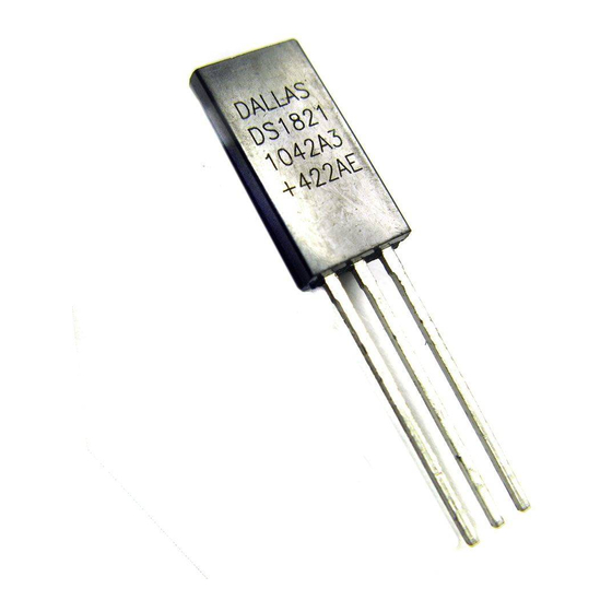
PR35
(DS1821)
- Ground
- Data In/Out and Thermostat Output
- Power Supply Voltage
- No Connect
DS1821
8
1
V
DD
7
2
NC
6
3
NC
5
4
NC
8-pin 208-mil SO
(DS1821S)
071107
Advertisement
Table of Contents

Summary of Contents for Dallas DS1821
-
Page 1: Pin Description
DS1821 units can be programmed prior to system insertion for true standalone operation. The DS1821 has an operating temperature range of –55°C to +125°C and is accurate to ±1°C over a range of 0°C to +85°C. Communication with the DS1821 is accomplished through the open-drain DQ pin; this pin also serves as the thermostat output. -
Page 2: Order Information
*All pins not specified in this table are “No Connect” pins. OVERVIEW Figure 1 shows a block diagram of the DS1821 and pin descriptions are given in Table 1. The DS1821 can operate as a standalone thermostat with user-programmable trip-points or as 8-bit temperature sensor with a 1-Wire digital interface. - Page 3 TL REGISTER TEMPERATURE SENSOR FUNCTIONALITY The core functionality of the DS1821 is its proprietary direct-to-digital temperature sensor, which provides 8-bit (1°C increment) centigrade temperature readings over the range of -55°C to +125°C. A block diagram of the temperature measurement circuitry is shown in Figure 2. This circuit measures the temperature by counting the number of clock cycles generated by an oscillator with a low temperature coefficient (temp-co) during a gate period determined by a high temp-co oscillator.
-
Page 4: Operating Modes
1-Wire MODE The DS1821 arrives from the factory in 1-Wire mode (T/R ¯ = 0). In this mode, the DQ pin of the DS1821 is configured as a 1-Wire port for communication with a microprocessor using the protocols described in the 1-Wire BUS SYSTEM section of this datasheet. -
Page 5: Thermostat Mode
1-byte (8-bit) temperature register (see Figure 3), which the user can access when the DS1821 is in 1-Wire mode (T/R ¯ = 0 in the status/configuration register). The sign bit (S) indicates if the temperature is positive or negative; for positive numbers S = 0 and for negative numbers S = 1. Table 2 gives examples of digital output data and the corresponding temperature reading. - Page 6 DS1821 TEMPERATURE/DATA RELATIONSHIP Table 2 TEMPERATURE DIGITAL OUTPUT DIGITAL OUTPUT (Binary) (Hex) +125°C* 0111 1101 +85°C 0101 0101 +25°C 0001 1001 0°C 0000 0000 -1°C 1111 1111 -25°C 1110 0111 -55°C 1100 1001 HIGH-RESOLUTION TEMPERATURE READINGS The user can calculate temperature values with higher than 8-bit resolution using the data remaining in the counter and slope accumulator when the temperature conversion is complete.
-
Page 7: Operation - Thermostat
DS1821 OPERATION – THERMOSTAT When the DS1821 is in thermostat mode (T/R ¯ = 1 in the status/configuration register), temperature conversions are performed continuously beginning at power-up (regardless of the value of the 1SHOT bit), and the DQ pin serves as the thermostat output. - Page 8 1 until it is over-written with a 0 by the user. T/R ¯ * — Power-up Operating Mode T/R ¯ = 0 — DS1821 powers up in 1- wire mode. (Read/Write) T/R ¯ = 1 — DS1821 powers up in thermostat mode.
-
Page 9: Hardware Configuration
The 1-Wire bus system uses a single bus master (i.e., a microprocessor) to control slave devices. The DS1821 functions as a slave device when it is used in 1-Wire mode; however, since the DS1821 is not addressable or multi-droppable, a single 1-Wire-mode DS1821 must be the only slave device on the bus. - Page 10 DS1821. The presence pulse lets the bus master know that the DS1821 is on the bus and ready to operate. Timing for the reset and presence pulses is detailed in the 1-Wire SIGNALING section.
- Page 11 DS1821. This is illustrated in Figure 7. When the DS1821 sends the presence pulse in response to the reset, it is indicating to the master that it is on the bus and ready to operate given an appropriate function command.
- Page 12 There are two types of write time slots: “Write 1” time slots and “Write 0” time slots. The bus master uses a Write 1 time slot to write a logic 1 to the DS1821 and a Write 0 time slot to write a logic 0 to the DS1821.
- Page 13 15 μs period. READ/WRITE TIME SLOT TIMING DIAGRAM Figure 8 LINE TYPE LEGEND (Figure 8, Figure 9 and Figure 10) Bus master pulling low DS1821 pulling low Resistor pullup START START...
- Page 14 DS1821 DS1821 OPERATION EXAMPLE In this example, the master device programs the DS1821 with T = +10°C and T = +40°C and verifies that the data has been saved correctly. The master then programs the status/configuration register so that the device will power-up in thermostat mode (T/R ¯ = 1) and the thermostat output will have active high polarity (POL = 1).
-
Page 15: Absolute Maximum Ratings
DS1821 ABSOLUTE MAXIMUM RATINGS* Voltage on any pin relative to ground –0.5V to +7.0V Operating temperature –55°C to +125°C Storage temperature –55°C to +125°C Soldering temperature See-JTD-020A Specification *These are stress ratings only and functional operation of the device at these or any other conditions above those indicated in the operation sections of this specification is not implied. -
Page 16: Ac Electrical Characteristics
DS1821 AC ELECTRICAL CHARACTERISTICS: (-55°C to +125°C; V =3.6V to 5.5V) PARAMETER SYMBOL UNITS NOTES Temperature Conversion Time CONV EEPROM Write Time Time Slot µs SLOT Recovery Time µs Write 0 Low Time µs LOW0 Write 1 Low Time µs... - Page 17 DS1821 TYPICAL PERFORMANCE CURVE Figure 11 MODE TOGGLE TIMING WHEN T/R ¯ = 1 Figure 12 17 of 18...
- Page 18 DS1821 TIMING DIAGRAMS Figure 13 18 of 18...
Need help?
Do you have a question about the DS1821 and is the answer not in the manual?
Questions and answers