Table of Contents
Advertisement
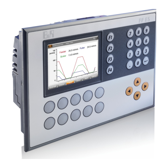
Power Panel 65
User's manual
Version: 2.21 (December 2016)
Model no.: MAPP65-ENG
Translation of the original documentation
The values and specifications listed in this manual are current as of its publication. We reserve the right
to change the contents of this manual without notice. Bernecker + Rainer Industrie-Elektronik Ges.m.b.H.
is not liable for technical/editorial errors and/or any incomplete information in this manual. In addition,
Bernecker + Rainer Industrie-Elektronik Ges.m.b.H. shall not be liable for any incidental or consequential damages
in connection with or arising from the furnishing, performance or use of the product(s) in this documentation. Soft-
ware names, hardware names and trademarks are registered by their respective companies.
Advertisement
Table of Contents

Summary of Contents for B&R Industrial Automation GmbH Power Panel 65
- Page 1 Power Panel 65 User's manual Version: 2.21 (December 2016) Model no.: MAPP65-ENG Translation of the original documentation The values and specifications listed in this manual are current as of its publication. We reserve the right to change the contents of this manual without notice. Bernecker + Rainer Industrie-Elektronik Ges.m.b.H.
- Page 2 Table of contents Power Panel 65 User's manual V2.21...
-
Page 3: Table Of Contents
2.6.5 Connection elements..........................40 2.6.6 Operating mode and node number switches..................42 2.6.7 Dimensions.............................. 43 2.7 4PP065.0571-X74............................44 2.7.1 Order data............................... 44 2.7.2 Technical data............................44 2.7.3 Supported interface modules........................46 2.7.4 Diagnostic LEDs............................46 Power Panel 65 User's manual V2.21... - Page 4 2.9.7 Operating mode and node number switches..................66 2.9.8 Dimensions.............................. 67 3 Interface modules....................69 3.1 General information............................69 3.2 Overview................................69 3.3 Power Panel 65 support..........................69 3.4 4PP065.IF10-1.............................. 70 3.4.1 Order data............................... 70 3.4.2 Technical data............................70 3.4.3 LED status indicators..........................71 3.4.4 RS232 interface............................
- Page 5 6.2 Replacement batteries..........................98 6.2.1 Order data............................... 98 6.2.2 Technical data............................98 6.2.3 Contents of delivery..........................98 6.3 TB103 3-pin power supply connector......................99 6.3.1 Order data............................... 99 6.3.2 Technical data............................99 6.3.3 Contents of delivery..........................100 Power Panel 65 User's manual V2.21...
- Page 6 7.4 Preventing screen burn-in on LCD/TFT displays..................108 7.4.1 How can this be avoided?........................108 8 Technical information................... 109 8.1 Surface resistance of the panel overlay..................... 109 8.2 Viewing angles............................109 9 Abbreviations......................111 9.1 General information.............................111 9.2 Overview..............................111 Power Panel 65 User's manual V2.21...
-
Page 7: General Information
October 2014 Updated chapter "Accessories". 2.00 February 2014 Updated the following chapters: • Technical data in chapter 2 "Power Panel 65" • Technical data in chapter 3 "PP65 interface modules" • Chapter 5 "Standards and certifications" • Chapter 6 "Accessories"... -
Page 8: Safety Guidelines
Electrical components with a housing • Do not touch the connector contacts on the device (bus data contacts). • Do not touch the connector contacts on connected cables. • Do not touch the contact tips on circuit boards. Power Panel 65 User's manual V2.21... -
Page 9: Policies And Procedures
• Electrical installation must be carried out in accordance with applicable guidelines (e.g. line cross sections, fuses, protective ground connections). • Take the necessary steps to protect against electrostatic discharges (see "Protection against electrostatic discharge" on page Power Panel 65 User's manual V2.21... -
Page 10: Operation
Programmable logic controllers Electronics recycling Operating/Monitoring devices Uninterruptible power supply Batteries and rechargeable batteries Cables Cardboard box / Paper packaging Cardboard box / Paper recycling Plastic packaging Plastic recycling Disposal must comply with applicable legal regulations. Power Panel 65 User's manual V2.21... -
Page 11: Organization Of Safety Notices
This information is important for preventing errors. Disregarding these safety guidelines and notices can be result in damage to property. Information: Tips for use and useful information. Does not contain information that warns against a danger- ous or damaging function. Power Panel 65 User's manual V2.21... -
Page 12: Terminology
PP65, PP100/200, PP300/400, MP100/200, EC20, EC21, AC140, AC141, ARsim, ARwin, ARemb, APC620, APC700, APC810 System Generation Compact CPUs (SGC) - CPUs with Motorola processors (Embedded µP) The following CPUs belong to this series: CP0201, CP0291, CP0292, XC0201, XC0202, XC0292 Table 1: Terminology Power Panel 65 User's manual V2.21... -
Page 13: Power Panel 65
Ethernet, POWERLINK and X2X Link are used for the communication system. Additionally, these devices have been equipped with a slot for interface modules. Depending on requirements, the Power Panel 65 can be expanded with CAN bus, a PROFIBUS DP slave or an RS485/RS232 interface, making it perfectly suited for demanding tasks. -
Page 14: General Technical Data
Power Panel 65 • System features 2.1.5 General technical data Name Description Geode LX800 500 MHz CPU Memory 128 MB SDRAM 232 kB SRAM, nonvolatile CompactFlash program memory Interfaces Ethernet 10/100 POWERLINK or X2X Link 2x USB 2.0 Slots CompactFlash slot... -
Page 15: Topologies
2.2 Topologies 2.2.1 Power Panel as intelligent HMI, networked with X2X Link and CAN In this topology, the control program and visualization application run on the Power Panel 65. I/O peripherals and drives are connected via CAN bus or X2X. -
Page 16: Power Panel As Intelligent Hmi, Networked With Powerlink
Power Panel 65 • Topologies 2.2.2 Power Panel as intelligent HMI, networked with POWERLINK In this topology, the control program runs on the Power Panel 65. I/O peripherals and drives are connected to the Power Panel via POWERLINK. Ethernet TCP/IP... -
Page 17: System Overview
Power Panel 65 • System overview 2.3 System overview 33 MHz 66 MHz 48 MHz 33 MHz Power Panel 65 User's manual V2.21... -
Page 18: 4Pp065.0351-P74
Battery Type Renata 950 mAh Service life 4 years Removable Yes, accessible from the outside Design Lithium ion Power button Reset button Backup capacitor Buffer time 10 min Table 3: 4PP065.0351-P74 - Technical data Power Panel 65 User's manual V2.21... - Page 19 Contrast 700:1 Viewing angles Horizontal Direction R / Direction L = 80° Vertical Direction U / Direction D = 80° Backlight Brightness 400 cd/m² Half-brightness time 50,000 h Table 3: 4PP065.0351-P74 - Technical data Power Panel 65 User's manual V2.21...
-
Page 20: Supported Interface Modules
Weight including fasteners and battery (46.5 g) but without an interface module. 2.4.3 Supported interface modules Support for interface modules is provided starting with the following Automation Runtime versions: Interface modules 4PP065.IF10-1 4PP065.IF23-1 4PP065.IF24-1 4PP065.IF33-1 Automation Runtime version A3.01 A3.01 A3.07 A3.01 Power Panel 65 User's manual V2.21... -
Page 21: Diagnostic Leds
This means that the configured station number lies within the range 0x01 - 0xFD. Blink code System error: The red blinking LED signals an error code (see "System failure error codes" on page 23). Power Panel 65 User's manual V2.21... - Page 22 Controlled node (CN) No output data is being produced, and no input data is being received. It is only possible to switch to or leave this state after the manager has given the appropriate command. Power Panel 65 User's manual V2.21...
-
Page 23: Connection Elements
POWERLINK interface 2.4.5.1 POWERLINK interface Interface Pinout Terminal POWERLINK Receive signal POWERLINK interface RXD\ Receive signal inverted Transmit signal Termination Termination Termination Termination TXD\ Transmit signal inverted Shielded RJ45 port Termination Termination Termination Termination Power Panel 65 User's manual V2.21... - Page 24 Power Panel 65 • 4PP065.0351-P74 2.4.5.2 USB interface This Power Panel 65 features a USB 2.0 (Universal Serial Bus) host controller with two USB ports that are acces- sible externally for the user. USB interface 1 USB interface 2 USB interface Transfer rate Low speed (1.5 Mbit/s), full speed (12 Mbit/s), high speed (480 Mbit/s)
-
Page 25: Key Assignments
2.4.7 Operating mode and node number switches The Power Panel 65 device is equipped with 2 hex switches that can be used as operating mode or node number switches. Switch positions 0x01 to 0xFE are used to set the INA station number of the Ethernet interface. -
Page 26: Dimensions
Power Panel 65 • 4PP065.0351-P74 2.4.8 Dimensions 109.5 27.3 Installation cutout: 188 ±0.5 mm x 130 ±0.5 mm Power Panel 65 User's manual V2.21... -
Page 27: 4Pp065.0351-X74
Battery Type Renata 950 mAh Service life 4 years Removable Yes, accessible from the outside Design Lithium ion Power button Reset button Backup capacitor Buffer time 10 min Table 5: 4PP065.0351-X74 - Technical data Power Panel 65 User's manual V2.21... - Page 28 Contrast 700:1 Viewing angles Horizontal Direction R / Direction L = 80° Vertical Direction U / Direction D = 80° Backlight Brightness 400 cd/m² Half-brightness time 50,000 h Table 5: 4PP065.0351-X74 - Technical data Power Panel 65 User's manual V2.21...
-
Page 29: Supported Interface Modules
Weight including fasteners and battery (46.5 g) but without an interface module. 2.5.3 Supported interface modules Support for interface modules is provided starting with the following Automation Runtime versions: Interface modules 4PP065.IF10-1 4PP065.IF23-1 4PP065.IF24-1 4PP065.IF33-1 Automation Runtime version C2.96 C2.96 A3.07 C2.96 Power Panel 65 User's manual V2.21... -
Page 30: Diagnostic Leds
There are two additional LEDs for the Ethernet interface. (green) (orange) Color Status Description Orange No Ethernet activity on the bus. Blinking Ethernet activity on the bus. Green Link established to the remote station Power Panel 65 User's manual V2.21... -
Page 31: Connection Elements
Terminal block accessory, 4-pin, cage clamps, 2.5 mm² 4-pin male multipoint connector 2.5.5.2 USB interface This Power Panel 65 features a USB 2.0 (Universal Serial Bus) host controller with two USB ports that are acces- sible externally for the user. USB interface 1... -
Page 32: Key Assignments
The functional ground must be connected to ground (e.g. control cabinet) using the shortest possible path. Using the largest possible conductor cross section on the supply connector is recommended. 2.5.6 Key assignments ◄ ↵ ▲ ► ▼ Power Panel 65 User's manual V2.21... -
Page 33: Operating Mode And Node Number Switches
2.5.7 Operating mode and node number switches The Power Panel 65 device is equipped with 2 hex switches that can be used as operating mode or node number switches. Switch positions 0x01 to 0xFE are used to set the INA station number of the Ethernet interface. -
Page 34: Dimensions
Power Panel 65 • 4PP065.0351-X74 2.5.8 Dimensions 109.5 27.3 Installation cutout: 188 ±0.5 mm x 130 ±0.5 mm Power Panel 65 User's manual V2.21... -
Page 35: 4Pp065.0571-P74
Design Lithium ion Backup capacitor Buffer time 10 min Certification cULus E115267 Industrial Control Equipment Controller Boot loader, operating system PP65 supported beginning with version Automation Runtime, A3.01 Table 7: 4PP065.0571-P74 - Technical data Power Panel 65 User's manual V2.21... - Page 36 50,000 h Touch screen Technology Analog, resistive Controller B&R, 12-bit Transmittance 70% ±10% Screen rotation Yes (see chapter "Installation", section "Screen rotation") Electrical characteristics Nominal voltage 24 VDC ±25% Table 7: 4PP065.0571-P74 - Technical data Power Panel 65 User's manual V2.21...
-
Page 37: Supported Interface Modules
A3.01 A3.01 A3.07 A3.01 2.6.4 Diagnostic LEDs There are four diagnostic LEDs on the back of the PP65. Information: The behavior of the Status LED has changed starting with AR J2.96, E3.01 and B3.06. Power Panel 65 User's manual V2.21... - Page 38 If an error occurs in the following statuses, then the green LED blinks over the red LED: • BASIC_ETHERNET • PRE_OPERATIONAL_1 • PRE_OPERATIONAL_2 • READY_TO_OPERATE Example: Status (green) Error (red) EPL LED Power Panel 65 User's manual V2.21...
- Page 39 ... 600 ms Pause ... 2 second delay Error description Error code displayed by red EPL LED RAM error ● ● ● Pause ● ● ● Pause Hardware error ● ● Pause ● ● Pause Power Panel 65 User's manual V2.21...
-
Page 40: Connection Elements
POWERLINK interface 2.6.5.1 POWERLINK interface Interface Pinout Terminal POWERLINK Receive signal POWERLINK interface RXD\ Receive signal inverted Transmit signal Termination Termination Termination Termination TXD\ Transmit signal inverted Shielded RJ45 port Termination Termination Termination Termination Power Panel 65 User's manual V2.21... - Page 41 Power Panel 65 • 4PP065.0571-P74 2.6.5.2 USB interface This Power Panel 65 features a USB 2.0 (Universal Serial Bus) host controller with two USB ports that are acces- sible externally for the user. USB interface 1 USB interface 2 USB interface Transfer rate Low speed (1.5 Mbit/s), full speed (12 Mbit/s), high speed (480 Mbit/s)
-
Page 42: Operating Mode And Node Number Switches
2.6.6 Operating mode and node number switches The Power Panel 65 device is equipped with 2 hex switches that can be used as operating mode or node number switches. Switch positions 0x01 to 0xFE are used to set the INA station number of the Ethernet interface. -
Page 43: Dimensions
Power Panel 65 • 4PP065.0571-P74 2.6.7 Dimensions 109.5 27.3 Installation cutout: 188 ±0.5 mm x 130 ±0.5 mm Power Panel 65 User's manual V2.21... -
Page 44: 4Pp065.0571-X74
Renata 950 mAh Service life 4 years Removable Yes, accessible from the outside Design Lithium ion Backup capacitor Buffer time 10 min Certification cULus E115267 Industrial Control Equipment Table 9: 4PP065.0571-X74 - Technical data Power Panel 65 User's manual V2.21... - Page 45 Direction U = 65° / Direction D = 50° Backlight Brightness 500 cd/m² Half-brightness time 50,000 h Touch screen Technology Analog, resistive Controller B&R, 12-bit Transmittance 70% ±10% Table 9: 4PP065.0571-X74 - Technical data Power Panel 65 User's manual V2.21...
-
Page 46: Supported Interface Modules
C2.96 C2.96 A3.07 C2.96 2.7.4 Diagnostic LEDs There are four diagnostic LEDs on the back of the PP65. Information: The behavior of the Status LED has changed starting with AR J2.96, E3.01 and B3.06. Power Panel 65 User's manual V2.21... -
Page 47: Connection Elements
Status Description Orange No Ethernet activity on the bus. Blinking Ethernet activity on the bus. Green Link established to the remote station 2.7.5 Connection elements Power supply Ethernet interface USB interfaces X2X Link interface Power Panel 65 User's manual V2.21... - Page 48 Terminal block accessory, 4-pin, cage clamps, 2.5 mm² 4-pin male multipoint connector 2.7.5.2 USB interface This Power Panel 65 features a USB 2.0 (Universal Serial Bus) host controller with two USB ports that are acces- sible externally for the user. USB interface 1...
-
Page 49: Operating Mode And Node Number Switches
2.7.6 Operating mode and node number switches The Power Panel 65 device is equipped with 2 hex switches that can be used as operating mode or node number switches. Switch positions 0x01 to 0xFE are used to set the INA station number of the Ethernet interface. -
Page 50: Dimensions
Power Panel 65 • 4PP065.0571-X74 2.7.7 Dimensions 109.5 27.3 Installation cutout: 188 ±0.5 mm x 130 ±0.5 mm Power Panel 65 User's manual V2.21... -
Page 51: Pp065.0571-P74F
Renata 950 mAh Service life 4 years Removable Yes, accessible from the outside Design Lithium ion Backup capacitor Buffer time 10 min Certification cULus E115267 Industrial Control Equipment Table 11: 4PP065.0571-P74F - Technical data Power Panel 65 User's manual V2.21... - Page 52 Direction U = 65° / Direction D = 50° Backlight Brightness 500 cd/m² Half-brightness time 50,000 h Touch screen Technology Analog, resistive Controller B&R, 12-bit Transmittance 70% ±10% Table 11: 4PP065.0571-P74F - Technical data Power Panel 65 User's manual V2.21...
-
Page 53: Supported Interface Modules
Weight including fasteners and battery (46.5 g) but without an interface module. 2.8.3 Supported interface modules Support for interface modules is provided starting with the following Automation Runtime versions: Interface modules 4PP065.IF10-1 4PP065.IF23-1 4PP065.IF24-1 4PP065.IF33-1 Automation Runtime version A3.01 A3.01 A3.07 A3.01 Power Panel 65 User's manual V2.21... -
Page 54: Diagnostic Leds
This means that the configured station number lies within the range 0x01 - 0xFD. Blink code System error: The red blinking LED signals an error code (see "System failure error codes" on page 56). Power Panel 65 User's manual V2.21... - Page 55 Controlled node (CN) No output data is being produced, and no input data is being received. It is only possible to switch to or leave this state after the manager has given the appropriate command. Power Panel 65 User's manual V2.21...
-
Page 56: Connection Elements
POWERLINK interface 2.8.5.1 POWERLINK interface Interface Pinout Terminal POWERLINK Receive signal POWERLINK interface RXD\ Receive signal inverted Transmit signal Termination Termination Termination Termination TXD\ Transmit signal inverted Shielded RJ45 port Termination Termination Termination Termination Power Panel 65 User's manual V2.21... - Page 57 Power Panel 65 • 4PP065.0571-P74F 2.8.5.2 USB interface This Power Panel 65 features a USB 2.0 (Universal Serial Bus) host controller with two USB ports that are acces- sible externally for the user. USB interface 1 USB interface 2 USB interface Transfer rate Low speed (1.5 Mbit/s), full speed (12 Mbit/s), high speed (480 Mbit/s)
-
Page 58: Key Assignments
2.8.7 Operating mode and node number switches The Power Panel 65 device is equipped with 2 hex switches that can be used as operating mode or node number switches. Switch positions 0x01 to 0xFE are used to set the INA station number of the Ethernet interface. -
Page 59: Dimensions
Power Panel 65 • 4PP065.0571-P74F 2.8.8 Dimensions 109.5 27.3 Installation cutout: 188 ±0.5 mm x 130 ±0.5 mm Power Panel 65 User's manual V2.21... -
Page 60: Pp065.0571-X74F
Red/Green Orange User Green Battery Type Renata 950 mAh Service life 4 years Removable Yes, accessible from the outside Design Lithium ion Backup capacitor Buffer time 10 min Table 13: 4PP065.0571-X74F - Technical data Power Panel 65 User's manual V2.21... - Page 61 Viewing angles Horizontal Direction R / Direction L = 60° Vertical Direction U = 65° / Direction D = 50° Backlight Brightness 500 cd/m² Half-brightness time 50,000 h Table 13: 4PP065.0571-X74F - Technical data Power Panel 65 User's manual V2.21...
-
Page 62: Supported Interface Modules
Weight including fasteners and battery (46.5 g) but without an interface module. 2.9.3 Supported interface modules Support for interface modules is provided starting with the following Automation Runtime versions: Interface modules 4PP065.IF10-1 4PP065.IF23-1 4PP065.IF24-1 4PP065.IF33-1 Automation Runtime version C2.96 C2.96 A3.07 C2.96 Power Panel 65 User's manual V2.21... -
Page 63: Diagnostic Leds
There are two additional LEDs for the Ethernet interface. (green) (orange) Color Status Description Orange No Ethernet activity on the bus. Blinking Ethernet activity on the bus. Green Link established to the remote station Power Panel 65 User's manual V2.21... -
Page 64: Connection Elements
Terminal block accessory, 4-pin, cage clamps, 2.5 mm² 4-pin male multipoint connector 2.9.5.2 USB interface This Power Panel 65 features a USB 2.0 (Universal Serial Bus) host controller with two USB ports that are acces- sible externally for the user. USB interface 1... -
Page 65: Key Assignments
Important! The functional ground must be connected to ground (e.g. control cabinet) using the shortest possible path. Using the largest possible conductor cross section on the supply connector is recommended. 2.9.6 Key assignments Power Panel 65 User's manual V2.21... -
Page 66: Operating Mode And Node Number Switches
2.9.7 Operating mode and node number switches The Power Panel 65 device is equipped with 2 hex switches that can be used as operating mode or node number switches. Switch positions 0x01 to 0xFE are used to set the INA station number of the Ethernet interface. -
Page 67: Dimensions
Power Panel 65 • 4PP065.0571-X74F 2.9.8 Dimensions 109.5 27.3 Installation cutout: 188 ±0.5 mm x 130 ±0.5 mm Power Panel 65 User's manual V2.21... -
Page 69: Interface Modules
3 Interface modules 3.1 General information Depending on the installed interfaces (Ethernet, X2X, USB), Power Panel 65 devices also provide an extra slot for interface modules. Depending on requirements, the Power Panel 65 can be expanded with CAN bus, a PROFIBUS DP slave or an RS485/RS232 interface, making it perfectly suited for demanding tasks. -
Page 70: Pp065.If10-1
10 to 90%, non-condensing Storage 10 to 90%, non-condensing Transport 10 to 90%, non-condensing Mechanical characteristics Weight 49 g Slot PP65 insert Torque for mounting screw Max. 0.6 Nm Table 15: 4PP065.IF10-1 - Technical data Power Panel 65 User's manual V2.21... -
Page 71: Led Status Indicators
Module receiving data via the RS232 interface Orange Module sending data via the RS232 interface 3.4.4 RS232 interface Interface Pinout RS232 RS232 interface Receive signal Transmit signal Ground Request To Send 9-pin male DSUB connector Clear To Send Power Panel 65 User's manual V2.21... -
Page 72: Pp065.If23-1
Max. distance 500 m Max. transfer rate 115.2 kbit/s Network-capable FIFO 16 bytes in transmit and receive direction Terminating resistor Integrated in the module Controller UART type 16C550 compatible Table 17: 4PP065.IF23-1 - Technical data Power Panel 65 User's manual V2.21... -
Page 73: Led Status Indicators
Module transmitting data via the X2X Link interface IF1 ... RS232 interface IF3 ... CAN bus interface 3.5.4 CAN bus node number The node number for the CAN bus interface is set with the two hex switches. Power Panel 65 User's manual V2.21... -
Page 74: Rs232 (If1) Or Rs485/Rs422 (If2) Interface
IF2 (RS485/RS422) and IF3 (CAN bus). IF2 (RS485/RS422) IF3 (CAN bus) Interface Switch position Description IF2 (RS485/RS422) Terminating resistor enabled (150 Ω) Terminating resistor disabled IF3 (CAN bus) Terminating resistor enabled (120 Ω) Terminating resistor disabled Power Panel 65 User's manual V2.21... -
Page 75: I/O Mapping In Automation Studio
Hexadecimal value of the node number switch. TerminatingResistor BOOL State of the switch for the IF3 terminating resistor: 0 ... OFF: Terminating resistor disabled 1 ... ON: Terminating resistor enabled TerminatingResistor only available in Automation Runtime A4.32 and later. Power Panel 65 User's manual V2.21... -
Page 76: Pp065.If24-1
500 m Max. transfer rate 115.2 kbit/s Network-capable FIFO 16 bytes in transmit and receive direction Terminating resistor Integrated in the module, switchable Controller UART type 16C550 compatible Table 19: 4PP065.IF24-1 - Technical data Power Panel 65 User's manual V2.21... -
Page 77: Led Status Indicators
IF3 ... PROFIBUS DP slave interface 3.6.4 PROFIBUS DP slave node number The node number for the PROFIBUS DP slave interface is set with the 2 hex switches. The AsL2DP library is used for the 4PP065.IF24-1. Power Panel 65 User's manual V2.21... -
Page 78: Rs232 (If1) Or Rs485/Rs422 (If2) Interface
IF2 (RS485) and IF3 (PROFIBUS DP). IF2 (RS485) IF3 (PROFIBUS DP slave) Interface Switch position Description Terminating resistor enabled (170 Ω) (RS485) Terminating resistor disabled Terminating resistor enabled (170 Ω) (PROFIBUS DP slave) Terminating resistor disabled Power Panel 65 User's manual V2.21... -
Page 79: I/O Mapping In Automation Studio
1 ... ON: Terminating resistor enabled TerminatingResistor only available in Automation Runtime A4.32 and later. I/O mapping for IF3 Interface IF3 is not shown in the I/O mapping in Automation Studio. This interface is operated using library AsL2DP. Power Panel 65 User's manual V2.21... -
Page 80: Pp065.If33-1
Bus length ≤200 m 250 kbit/s Bus length ≤1000 m 50 kbit/s Operating conditions Protection IP20 Environmental conditions Temperature Operation 0 to 50°C Storage -25 to 70°C Transport -25 to 70°C Table 21: 4PP065.IF33-1 - Technical data Power Panel 65 User's manual V2.21... -
Page 81: Led Status Indicators
The node number for the CAN bus interfaces is set with the two hex switches. The configured node number applies to both interfaces. 3.7.5 CAN bus interface (IF1 and IF2) Interface Pinout CAN bus CAN bus interface CAN_H CAN high CAN⊥ CAN ground CAN_L CAN low SHLD Shield 4-pin male multipoint connector Power Panel 65 User's manual V2.21... -
Page 82: Terminating Resistors
Hexadecimal value of the node number switch (identical with NodeSwitch of IF1). TerminatingResistor BOOL State of the switch for the IF2 terminating resistor: 0 ... OFF: Terminating resistor disabled 1 ... ON: Terminating resistor enabled TerminatingResistor only available in Automation Runtime A4.32 and later. Power Panel 65 User's manual V2.21... -
Page 83: Installation
40 mm spacing 40 mm spacing Table 22: Spacing for air circulation - Rear view Side view Air outlet At least 80 mm spacing Air intake Table 23: Spacing for air circulation - Side view Power Panel 65 User's manual V2.21... -
Page 84: Mounting Orientations
2) Remove the cover. 3) Insert the interface module into the PP65. 4) Apply light pressure until the interface module is inserted all the way. 5) Secure the interface module with the screws (max. 0.6 Nm). Power Panel 65 User's manual V2.21... -
Page 85: Touch Screen Calibration
It is possible to rotate the contents of the screen by 90° using the graphic driver's screen rotation function. This function is supported by Automation Runtime. In Automation Studio 2.7.x or 3.0.x, the screen orientation can be defined when a project is created or later when editing the project. Power Panel 65 User's manual V2.21... -
Page 87: Standards And Certifications
• EMC directive 89/336/EEC • Low-voltage directive 73/23/EEC • Machine directive 98/37/EC 5.2 Overview of standards Power Panel 65 devices meet the following standards: Standard Description EN 55011 Electromagnetic compatibility (EMC), radio disturbance product standard, industrial, scientific, and medical high-frequency de- Class A, B vices (ISM devices), limit values and measurement procedure;... -
Page 88: Emission Requirements
10 m Quasi-peak value 216 to 960 MHz <210 dB (μV/m) measured at a distance of 10 m Quasi-peak value >960 MHz <300 dB (μV/m) measured at a distance of 10 m Quasi-peak value Power Panel 65 User's manual V2.21... -
Page 89: Requirements For Immunity To Disturbances
3 seconds, criteria A 1 kHz, duration 3 seconds, criteria A 1 kHz, duration 3 seconds, criteria A 800 to 960 MHz (GSM), 10 V/m, pulse modulation with 50% duty cycle, criteria A Power Panel 65 User's manual V2.21... -
Page 90: High-Speed Transient Electrical Disturbances (Burst)
AC power inputs Voltage dip <5% (>95% reduction), 250 periods, criteria C AC power inputs 20 interruptions, 0.5 periods, criteria A DC mains inputs 20 interruptions for 10 ms, <UN - 15%, criteria A Power Panel 65 User's manual V2.21... -
Page 91: Damped Vibration
Devices: Drop/topple on each edge Weight Required Weight Required Weight Required <20 kg <20 kg <20 kg 20 to 100 kg 20 to 100 kg 20 to 100 kg >100 kg >100 kg >100 kg Power Panel 65 User's manual V2.21... -
Page 92: Free Fall (Packaged)
Limits in accordance with dance with EN 61131-2 EN 60068-2-14 Large temperature fluctuations 3 hours at -40°C and 3 hours at 70°C for 2 cycles, then 2 hours acclimatization and function testing, duration approx. 14 hours Power Panel 65 User's manual V2.21... -
Page 93: Temperature Fluctuations In Operation
NEMA 250 type 4X UL 508 Sprayed water (front side) Sprayed with a 25.4 mm (diameter) nozzle Distance: 3 to 3.7 m (all angles), water volume: 246 liters/minute Duration: 48 seconds, 5 seconds minimum Power Panel 65 User's manual V2.21... -
Page 94: Safety
24 VDC -15% 48 VDC +20% 125 VDC 24 VAC -15% 48 VAC +10% 100 VAC 110 VAC 120 VAC 200 VAC 230 VAC 240 VAC 400 VAC Table 24: Safety - Voltage range Power Panel 65 User's manual V2.21... -
Page 95: Other Tests
ISO, IEC and CENELEC, as well as national standards from organizations such as UL, CSA, VDE, ÖVE, etc. We are committed to ensuring the reliability of our products in an industrial environment. Certifications Europe This mark certifies that all harmonized EN standards for the applicable directives have been met. Power Panel 65 User's manual V2.21... -
Page 97: Accessories
0G0001.00-090 PC - PLC/PW cable, RS232, online cable ● ● ● 0AC913.93 Bus adapter, CAN, 2 CAN interfaces, including 30 cm attachment cable (TB704) ● ● 0G1000.00-090 Bus connector, RS485, for PROFIBUS networks ● Power Panel 65 User's manual V2.21... -
Page 98: Replacement Batteries
Storage 0 to 95% Transport 0 to 95% Table 26: 0AC201.91, 4A0006.00-000 - Technical data 6.2.3 Contents of delivery Quantity Component 1 or 4 Lithium batteries Table 27: 0AC201.91, 4A0006.00-000 - Contents of delivery Power Panel 65 User's manual V2.21... -
Page 99: Tb103 3-Pin Power Supply Connector
Yes, although applies only if all components installed within the complete system have this certification and the complete system itself carries the corresponding mark. Cage clamp terminal blocks cannot be used side-by-side. The limit data for each I/O module must be taken into consideration. Power Panel 65 User's manual V2.21... -
Page 100: Contents Of Delivery
Accessories • TB103 3-pin power supply connector 6.3.3 Contents of delivery Quantity Component Power connector in desired design. Table 30: 0TB103.9, 0TB103.91 - Contents of delivery Power Panel 65 User's manual V2.21... -
Page 101: Tb704 4-Pin X2X Link Connector
Cage clamp terminal blocks cannot be used side-by-side. The limit data for each I/O module must be taken into consideration. 6.4.3 Contents of delivery Quantity Component Terminal in desired design. Table 33: 0TB704.9, 0TB704.91 - Contents of delivery Power Panel 65 User's manual V2.21... -
Page 102: Slide-In Label Templates
Technical data and additional information about data storage media can be found in the respective documentation. This can be found and downloaded under the model number of the data storage medium on the B&R website at www.br-automation.com. Power Panel 65 User's manual V2.21... -
Page 103: Maintenance
(ethanol). The cleaning agent should be applied to the cloth beforehand, not sprayed directly on the Power Panel! Aggressive solvents, chemicals, scouring agents, pressurized air or steam jets should never be used. Information: Displays with a touch screen should be cleaned regularly. Power Panel 65 User's manual V2.21... -
Page 104: Replacing The Battery
• Touch the housing or ground connection in order to discharge any electrostatic charge from your body. • Remove the battery cover from the top of the Power Panel device using a screwdriver (1). Figure 2: Replacing the battery - Removing the battery cover Power Panel 65 User's manual V2.21... - Page 105 • Reconnect the power supply to the Power Panel. • Reset the date and time (using B&R Automation Studio). Warning! Lithium batteries are considered hazardous waste. Used batteries should be disposed of in accordance with applicable local regulations. Power Panel 65 User's manual V2.21...
-
Page 106: Replacing The Compactflash Card
Rotate the orange CompactFlash safety latch away from the CompactFlash slot (1). Then press the CompactFlash ejection lever (2) with a screwdriver until the CompactFlash card is ejected. The CompactFlash card can now be removed by hand (3). Power Panel 65 User's manual V2.21... -
Page 107: Inserting The Compactflash Card
If inserted incorrectly, the CompactFlash card will not go in all the way and the ejection lever will not extend out. Finally, rotate the safety latch over the CompactFlash slot (3) to secure the CompactFlash card (4). Power Panel 65 User's manual V2.21... -
Page 108: Preventing Screen Burn-In On Lcd/Tft Displays
• Use non-static screensavers when the display is not in use. • Frequent picture change • Turn off the display when not in use. Turning off the backlight does not help prevent screen burn-in. Power Panel 65 User's manual V2.21... -
Page 109: Technical Information
The panel overlay conforms to DIN 42115 Part 2 for exposure to glacial acetic acid for less than one hour without visible damage. 8.2 Viewing angles Viewing angle specifications (R, L, U, D) for the display types are listed in the technical data for each device. Facing 6 o'clock Figure: Viewing angles Power Panel 65 User's manual V2.21... -
Page 111: Abbreviations
A normally open relay contact To be defined Used in technical data tables when certain information is not yet available. The value will be provided later. Table 37: Abbreviations used in this user's manual Power Panel 65 User's manual V2.21... - Page 112 Model number index 0AC201.91................................98 0TB103.9................................99 0TB103.91................................99 0TB704.9................................101 0TB704.91................................101 4A0006.00-000............................... 98 4PP065.0351-P74..............................18 4PP065.0351-X74..............................27 4PP065.0571-P74..............................35 4PP065.0571-P74F..............................51 4PP065.0571-X74..............................44 4PP065.0571-X74F..............................60 4PP065.IF10-1............................... 70 4PP065.IF23-1............................... 72 4PP065.IF24-1............................... 76 4PP065.IF33-1............................... 80 Power Panel 65 User's manual V2.21...
Need help?
Do you have a question about the Power Panel 65 and is the answer not in the manual?
Questions and answers