Advertisement
ET BLUE-ROLL
Domestic type roll-up garage door operator
Installation manual
Revision Oct.08.002
support@et.co.za
Technical specifications may change without prior notice.
All goods are subject to the standard factory warranty as laid out on the last page of this publication
G&C Electronics cc. T/A ET Systems
15 Nelson Rd, Observatory, Cape Town, South Africa
www.et.co.za
1
Advertisement
Table of Contents

Summary of Contents for Et BLUE-ROLL
- Page 1 Technical specifications may change without prior notice. All goods are subject to the standard factory warranty as laid out on the last page of this publication G&C Electronics cc. T/A ET Systems 15 Nelson Rd, Observatory, Cape Town, South Africa...
- Page 2 We strongly recommend that a set of safety infra red beams (ET BLUE I’s) be used for additional protection. DO NOT operate the Garage door operator while a person, especially a child is near the door. Children must be under adult supervision at all times near an automated garage door especially whilst the operator is in use.
-
Page 3: Pre-Installation Instructions
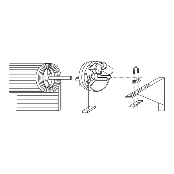
PRE-INSTALLATION INSTRUCTIONS 1. PRE-INSTALLATION PREPARATION 1.1. Ensure sufficient side room space: Minimum side room of 85mm from the face of the door drum wheel to the inside edge of the door support bracket is required to install the opener (see Fig. 1) and maximum side room is 125mm before having to move and re-fit the support bracket or install the drive unit fully inside the drum (Fig. -
Page 4: Installation Instructions
INSTALLATION INSTRUCTIONS WARNING: EXTREME CARE SHOULD BE TAKEN TO PREVENT ANY POSSIBLE DAMAGES INSTALLING THE OPENER ONTO THE DOOR SHAFT There are various methods on how to install an opener to the door. The following is the most typical method. CAUTION: THE INSTRUCTIONS SHOWN HERE ARE FOR RIGHT-HAND INSTALLATION 2.1 Roll the door up until the door curtain is out the door guides / tracks and use a rope to firmly tighten the roll in the middle of the door (see Fig. - Page 5 2.5 Switch the opener into manual operation mode by pulling the manual release handle to enable the opener drive to rotate freely. 2.6 Raise the door carefully, insert the opener into the door axle and ensure the two opener forks hold the door drum wheel support.
- Page 6 PIN DOOR CURTAIN TO DOOR DRUM WHEEL 3.1 Pinning the door curtain to the drum wheel will reduce possible forced lifting of the door. Close the door to the fully closed position and mark the two positions where the curtain is to be pinned onto the drum wheel on either side of the door.
-
Page 7: The Control Unit
THE CONTROL UNIT. Fig. 10 Light fitting Light cover lens Batteries Control card Transformer behind control card Drive unit cable inlet 220V mains cable inlet Antenna Light cover lens fastening screw Main control cover 11 Main control cover fastening screw... - Page 8 CONNECT THE DRIVE UNIT CABLE TO THE CONTROL CARD AS PER FIG. 12 OR FIG. 13 TO CONTINUE. NB. The motor wiring of a right hand installation differs to that of a left hand installation! Figures 12 and 13 below indicate the wiring requirements for either left or right handed type installations. Fig.
- Page 9 Autoclose jumper On = active (20secs and pre-beep warning) BT + centre = Button trigger function (25 users) Receiver programming pins LT + centre = Courtesy light function (6 users) Receiver programming and detect LED See table under receiver programming section below Onboard test button Functions as per transmitter BT 220Vac mains fuse...
- Page 10 Fig. 12 Left hand installation Fig. 13 Red 0.75mm Motor Right hand installation Yellow 0.75mm Motor White 0.3mm Limit common Brow n 0.3mm Open limit Green 0.3mm Closed limit...
- Page 11 Load sensing P.O.T: Used to adjust the amount of obstruction sensitivity necessary to initiate the automatic safety routine. NB! The ET BLUE ROLL automatically sets its own opening load sensing off the closing setting. When adjusting the load sensing use the closing direction! When closing, the door will stop and reverse on sensing an obstruction.
- Page 12 Motor output fuse: If blown replace with an 8A fast blow fuse only. This fuse will normally blow if the maximum resistive load (Heavy door action/obstruction) is exceeded. Battery low beep override jumper: If the unit has been installed without batteries, place the jumper across the pins here.
- Page 13 Adjusting the open and closed limit positions: Fig. 14 Fig. 15 Accessing the limit switches Loosen the limit cams Fig. 16 SETTING THE DOOR TRAVEL LIMITS. A: RIGHT-HAND SIDE INSTALLATION. Remove the back cover from the opener (Fig 14). Pull the manual release handle to change opener to the manual operation mode.
- Page 14 8.3 Slightly re-tighten the two wing-nuts 8.4 Power controller up by connecting the mains power first and then the battery leads 8.5 Pull the manual release handle to change the opener back to automatic mode. Testing and adjusting travel limit settings (RIGHT-HAND fit): 8.6 Close position: Press and release the onboard test button.
-
Page 15: General Maintenance
GENERAL MAINTENANCE: 10 The following should be conducted MONTHLY 10.1 Safety reverse test. Repeat the test (see F control card features) and make adjustments if necessary. 10.2 Door manual operation test. Manually open and close the door. Check to ensure door is not too heavy or over tensioned, difficult to close (should be less than 15kg operating force in general), unbalanced or binding due to loss of tension in the spring. - Page 16 You may be asked to take readings with a multi-meter. Please have one handy. If you are not proficient in the use of a multi-meter please contact a service provider in your area. Your nearest ET Systems branch will have contact details of preferred service providers in your area.
- Page 17 ET Systems free of charge. This warranty is subject to the goods being returned to the premises of ET Systems. The carriage of goods is for the customers account. This warranty is only valid if the correct installation and application of goods, as laid out in the applicable documentation accompanying said goods, is adhered to.
Need help?
Do you have a question about the BLUE-ROLL and is the answer not in the manual?
Questions and answers