Table of Contents
Advertisement
Advertisement
Table of Contents

Summary of Contents for Shadin Avionics 943200-11
- Page 1 ETM RECORDER P/N: 943200-11 INSTALLATION MANUAL MANUAL P/N: M943200-11 REV – SHADIN AVIONICS 6831 Oxford Street St. Louis Park, MN 55426-4412 Sales: (800) 328-0584 Customer Service: (800) 388-2849 SHADIN AVIONICS www.shadin.com Customer Service: (952) 836-2269 service@shadin.com...
- Page 2 943200-11 ETM RECORDER DOCUMENT INSTALLATION MANUAL Control SC1 Revision – M943200-11 Page: 2 of 17 digitally signed by ShadinCM-zk 2018.06.25 14:45:57 REVISION LOG -05'00' Date DESCRIPTION – 21 JUN 2018 1804/005 Initial Issue SHADIN AVIONICS www.shadin.com Customer Service: (952) 836-2269...
-
Page 3: Table Of Contents
943200-11 ETM RECORDER DOCUMENT INSTALLATION MANUAL Control SC1 Revision – M943200-11 Page: 3 of 17 TABLE OF CONTENTS 1 OVERVIEW ........................4 1.1 SCOPE ..........................4 1.2 PRODUCT DESCRIPTION ....................4 2 SPECIFICATIONS ......................6 2.1 PHYSICAL ......................... 6 2.2 ELECTRICAL ........................6 2.3 ENVIRONMENTAL ...................... -
Page 4: Overview
The information in this manual is subject to change without notification. SCOPE This manual describes the interface to the 943200-11 ETM Recorder. It also provides information to guide the proper installation of the Engine Trend Monitor (ETM) Recorder. Installation instructions should be read and followed. - Page 5 943200-11 ETM RECORDER DOCUMENT INSTALLATION MANUAL Control SC1 Revision – M943200-11 Page: 5 of 17 USB Port The ETM Recorder utilizes an industry standard USB port interface to extract a copy of the Report files off the ETM Recorder. The Report files contained on the ETM Recorder can be extracted by connecting a USB Flash drive to the ETM Recorder USB port.
-
Page 6: Specifications
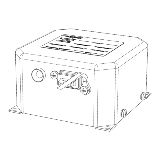
943200-11 ETM RECORDER DOCUMENT INSTALLATION MANUAL Control SC1 Revision – M943200-11 Page: 6 of 17 SPECIFICATIONS For a complete listing of product qualifications please review the Environmental Qualification Form found in Section 4. PHYSICAL 3.18”L x 3.18”W x 1.80”H Nominal Dimensions: Weight: 0.35 pounds... -
Page 7: Installation
943200-11 ETM RECORDER DOCUMENT INSTALLATION MANUAL Control SC1 Revision – M943200-11 Page: 7 of 17 INSTALLATION LIMITATIONS The conditions and tests required for TSO approval of this article are minimum performance standards. It is the responsibility of those installing this article either on or within a specific type or class of aircraft to determine that the aircraft installation conditions are within the TSO standards. -
Page 8: Typical Installation Wiring
943200-11 ETM RECORDER DOCUMENT INSTALLATION MANUAL Control SC1 Revision – M943200-11 Page: 8 of 17 3.3.1 TYPICAL INSTALLATION WIRING Figure 2 is typical installations wiring diagram. AIRCRAFT INPUTS ETM Recorder 943200-11 USB Flash Drive RX RS-232 Shadin Avionics Engine Trend Monitor... -
Page 9: Environmental Qualification Form
943200-11 ETM RECORDER DOCUMENT INSTALLATION MANUAL Control SC1 Revision – M943200-11 Page: 9 of 17 ENVIRONMENTAL QUALIFICATION FORM The ETM RECORDER hardware was environmentally tested with all functions active to RTCA/DO-160G and is documented in Shadin Qualification Test Reports. NOMENCATURE: ETM RECORDER... -
Page 10: Etm Recorder Setup
943200-11 ETM RECORDER DOCUMENT INSTALLATION MANUAL Control SC1 Revision – M943200-11 Page: 10 of 17 ETM RECORDER SETUP INITIAL SETUP 5.1.1 ETM RECORDER SETUP The ETM Recorder does not require initial setup. The unit becomes active and ready when power is applied to its power pins. -
Page 11: Etm Setup
943200-11 ETM RECORDER DOCUMENT INSTALLATION MANUAL Control SC1 Revision – M943200-11 Page: 11 of 17 5.1.3 ETM SETUP The following steps describe how to configure the ETM for use with the ETM Recorder. Display The display of the ETM contains two lines, 12 characters per line. -
Page 12: 5.1.3.1 Set Etm Output Select To Printer Mode
943200-11 ETM RECORDER DOCUMENT INSTALLATION MANUAL Control SC1 Revision – M943200-11 Page: 12 of 17 5.1.3.1 SET ETM OUTPUT SELECT TO PRINTER MODE It is required that an ETM is configured to “Printer” mode prior to use with the ETM Recorder. -
Page 13: 5.1.3.3 Set Engine Serial Numbers
943200-11 ETM RECORDER DOCUMENT INSTALLATION MANUAL Control SC1 Revision – M943200-11 Page: 13 of 17 5.1.3.3 SET ENGINE SERIAL NUMBERS It is recommended that engine serial numbers are loaded in the ETM prior to use with the ETM Recorder. The ETM records contain engine serial numbers for trend data analysis. -
Page 14: Operational Modes And Procedures
943200-11 ETM RECORDER DOCUMENT INSTALLATION MANUAL Control SC1 Revision – M943200-11 Page: 14 of 17 OPERATIONAL MODES AND PROCEDURES The ETM Recorder will enter one of two operational modes at power up, Record mode or USB Data Download mode. The ETM Recorder will remain in the same mode until power is cycled. The ETM Recorder software determines the mode by trying to access the external USB Flash drive when power is first applied. -
Page 15: Troubleshooting
943200-11 ETM RECORDER DOCUMENT INSTALLATION MANUAL Control SC1 Revision – M943200-11 Page: 15 of 17 TROUBLESHOOTING This section provides some methods for troubles shooting the ETM Recorder. IF NO FILES ARE ON THE USB FLASH DRIVE A. Verify the USB Flash drive was not left in the ETM Recorder during a flight. -
Page 16: Appendix A: Installation Drawing
943200-11 ETM RECORDER DOCUMENT INSTALLATION MANUAL Control SC1 Revision – M943200-11 Page: 16 of 17 APPENDIX A: INSTALLATION DRAWING Installation drawing D943200-11 can be found on the next page. SHADIN AVIONICS www.shadin.com Customer Service: (952) 836-2269 service@shadin.com... - Page 17 MOUNTING SCREW SIZE IS NO. 6 DRAWN PER ASME Y14.5M-2009 INSTALLATION DWG, DIMENSIONS ARE IN INCHES 3. WEIGHT: 0.35 LBS TOLERANCES: THIRD ANGLE ST. LOUIS PARK, MN 55426 P/N 943200-11 1/64 PROJECTION J1 CONNECTOR 4/10/2018 DRAWN -15 PIN D-SUB, MALE 4/11/2018 CHECKED X.XX...
Need help?
Do you have a question about the 943200-11 and is the answer not in the manual?
Questions and answers