Advertisement
Table of Contents
- 1 Table of Contents
- 2 Introduction
- 3 General Information
- 4 General Safety Information
- 5 Installation Instructions
- 6 Maintenance Instructions
- 7 Product Disposal
- 8 Appendix 1 - Technical Data and Dimensions
- 9 Appendix2-ListOfR EcommendedInverters
- 10 Appendix 3 - Drawings of Fixing Parts
- Download this manual
Advertisement
Table of Contents

Summary of Contents for Pramac LUCE MCPH P7
- Page 1 MICROMORPH PHOTOVOLTAIC MODULE ® PRAMAC LUCE MCPH P7 USER MANUAL...
- Page 2 ...
- Page 3 PRAMAC SWISS S.A. PRAMAC SWISS S.A. reserves the right to modify and upgrade its products, at any time and without advance notice, for the purpose of continuous quality enhancement. Hence, subsequent editions of this document may be subject to revision or change ©...
-
Page 4: Table Of Contents
ENGLISH 4 Contents Introduction ............................... 5 General Information ............................ 7 General Safety Information .......................... 8 Installation Instructions ........................... 1 0 Preliminary operations .......................... 1 0 Instructions for Mechanical Installation ...................... 1 3 Instructions for Electrical Installation ...................... 1 8 Maintenance Instructions .......................... 2 2 Product Disposal ............................. 2 3 Appendix 1 – Technical data and dimensions ... -
Page 5: Introduction
ENGLISH 5 Introduction Before product installation, use and maintenance, read carefully these instructions and scrupulously comply with all the safety precautions herein prescribed. These instructions provide all the information required to guarantee correct installation and use of the product, ensuring user safety as well. Compliance with the provisions set forth in this document will also ensure optimal product performance and guarantee this performance over time by following simple periodical maintenance procedures. ... - Page 6 ENGLISH 6 Safety Symbols These instructions contain warnings accompanied by three symbols, described hereafter. DANGER The warnings preceded by this symbol specifically refer to situations of impending danger, with the possibility of serious physical injury to persons or risk of death. RISK The warnings preceded by this symbol specifically refer to risk situations, with the possibility of serious physical injury to persons and damage to the product, resulting in loss of safety conditions. NOTE The warnings preceded by this symbol serve to focus attention on important information, mainly of a technical nature. ...
-
Page 7: General Information
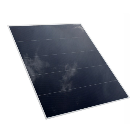
The commercial denomination of the product is: PRAMAC LUCE MCPH P7. PRAMAC LUCE MICROMORPH® MCPH P7 modules are manufactured using silicon Thin Film Tandem Junction technology. This process combines an amorphous silicon top layer over a microcrystalline silicon layer. The top cell absorbs and convert the visible radiations of the solar ... -
Page 8: General Safety Information
ENGLISH 8 General Safety Information Allowed use The photovoltaic module, used alone or in combination with one or more modules of the same type, is designed for the purpose of producing electric energy when exposed to sunlight. The module is designed to be connected in series and/or in parallel to others panels only made by the same technology and together connected to a DC/AC converter (inverter). Any other use is strictly forbidden and could engender risks for user safety and damage to the product. ... - Page 9 ENGLISH 9 DANGER Product installation carried out by unqualified personnel is explicitly forbidden. The manufacturer declines any responsibility for injury to persons and/or animals and/or damage to property caused by improper installation of the product. Installation precautions Proper installation requires the knowledge of the overall dimensions of the product to guarantee correct installation and leave sufficient clearance space for standard product use. Please use only tools in good conditions and use all personal protection equipment required by local regulations. If modules are installed above ground level, wear a safety belt and protection gloves when installing the modules to prevent the risk of falling and electric shock. DANGER Electric current may cause serious personal injury. If the front or back glass is broke, as well as the j‐Box, the contact with any part of the module may result in ...
-
Page 10: Installation Instructions
ENGLISH 10 Installation Instructions Preliminary operations Check packaging! Please check contents if box is visibly damaged. Check cables, connectors and the module on both sides for damages. Do not install damaged modules. Maximum care must be used during product transportation, storage and unpacking. If the modules must be temporarily stored, keep them in a dry and ventilated environment. The installer or purchaser are responsible for choosing the location where the structure and supports are to be mounted and for preparing the relative layout. During module installation, please respect all local, regional and national applicable safety regulations, including construction codes and regulations, where required. Use appropriate safety equipment (insulated tools, insulated gloves, etc.), approved for use on electric equipment and systems. Please follow all instructions and comply with all safety precautions prescribed for all other components used in the system. ... - Page 11 ENGLISH 11 Important notice RISK Do not paint or apply adhesives to the modules (especially on the front glass). RISK Each module may generate voltage in excess of 100 V once exposed to a source of direct or indirect light. Be careful during module handling or wiring if the modules are exposed to sunlight. Do not wear rings or metal objects during panel installation or maintenance. RISK Do not use mirrors or other artificial methods aimed at amplifying and concentrating light on the modules. ...
- Page 12 ENGLISH 12 RISK Absolutely avoid dropping the module or bumping it during handling and assembly. Do not put modules down on edges unprotected. Do not assemble damaged modules. RISK Do not submerge the module in water nor subject the module to a constant stream of water. ...
-
Page 13: Instructions For Mechanical Installation
ENGLISH 13 Instructions for Mechanical Installation PV modules are exposed to a wide range of mechanical conditions, so that surface stress may appear. Due to the different thermal coefficients of glass and metal structures, thermal stress can occur as a result of the module outdoor exposure. National Codes Standards (EuroCode EN 1991, DIN 1055, etc.) set basics rules to be followed for the planning of a structural framework and the building of structures. Modules must be securely fixed and should not be in direct contact with metal parts. All direct contacts ... - Page 14 ENGLISH 14 Procedure 1. The supporting structure must be composed of 3 lengthwise sections at least 6 cm wide. 2. The direct contact between the module and the metal support has to be avoided: apply on the back rails a layer of protective Ethylene‐Propylene‐Diene‐Monomer rubber ( 1100 x 15 x 2 mm dimensions). 3. Before positioning the PV panel, fix up the horizontal lower supporting clamps without fixing them firmly. ...
- Page 15 5. Proceed adding the upper clamps and the lateral fixing bar. Finally fix up firmly all the clamps. Vertical fixing bars are fixed on the frame in 3 points. NOTE: Tighten the screws with the torque provided by the manufacturer for the hardware used. Pramac recommend bolts and nuts with guaranteed mechanical characteristics, with a bolt/nut friction factor constant and known. Ex: Bolts M8 ‐ Class 4.8 – factor 0.20 → fric on torque = 14.3 Nm ...
- Page 16 ENGLISH 16 6. Repeat the same procedure for the next modules. For centrals panels, ‘omega’ shaped vertical bars are available allowing the fixing of two modules at the same time, reducing considerably the amount of material, the cost and the fixing time. For other kinds of configurations also ‘omega’ shaped horizontals clamps are available. ...
- Page 17 ENGLISH 17 RISK The module must be installed taking into account its thermal features. In order to guarantee air flow around the module, sufficient room must be provided between the panel and the mounting system. This room will allow heat dissipation and will limit the creation of condensation and humidity. Furthermore, to avoid mechanical failures, modules must be spaced to allow thermal expansion. RISK The structure on which the modules (or a single module) shall be mounted must have resting points that are perfectly coplanar between themselves. When tightening clamps or bolts for assembly, absolutely avoid applying a torque that may risk breaking the module (see point 5 of mounting procedure). RISK Partial shading on modules must be absolutely avoided, in particular a shading area which is ...
-
Page 18: Instructions For Electrical Installation
ENGLISH 18 Instructions for Electrical Installation When designing the system, avoid ground loops. The negative effects of partial shading on power generation can be minimised through accurate routing of each string. Before connecting the strings to the inverter, make sure that the wiring has been carried out correctly. If the open‐circuit voltage (Voc) or the short circuit current (Isc) differ from those indicated in the specifications, do not connect the system and check the wiring. During installation, rigorously check all the electrical connections and the connectors airtight lock. Electric cables must not be subject to stress or mechanical loads and the connectors must be used only ... - Page 19 ENGLISH 19 Installation layout: series/parallel connections Series If the modules are connected in series, the overall voltage may reach high values. When this type of layout is used, the equivalent voltage is the sum of the voltage of each individual panel. Only modules with identical current characteristics must be connected in series. ...
- Page 20 ENGLISH 20 Parallel For applications which require high current, modules can be connected in parallel and the overall current will be equal to the sum of the currents of each panel. RISK Parallel connections can be set only if modules voltage characteristics are identical. A parallel connection is allowed for up to 3 strings as a maximum. If the installation requires a higher amount of parallel connected strings, then a blocking diode every 3 strings is required. NOTE Modules of a string must have identical orientation and inclination. Inverters Inverters convert direct current into alternating current. Inverters of the latest generation, thanks to ...
- Page 21 ENGLISH 21 NOTE Always connect the converter when installation is complete and after checking all the cablings. Ground connections To avoid corrosion of the TCO layer and consequently a permanent failure of the photovoltaic module, the negative terminal should be grounded. In view of the above, it is mandatory to install an inverter with galvanic isolation to ensure safety. NOTE MCPH PV modules are compatible and must be connected only to inverters with transformer included. DANGER Make all connections according to local regulation for compliance and safety of electrical installations. ...
-
Page 22: Maintenance Instructions
ENGLISH 22 Maintenance Instructions We recommend inspecting the system periodically (every 12 months). We further recommend the following maintenance operations in order to guarantee maximum module performance: 1. Clean the glass surface when required. Use water and a sponge (or a soft cloth). A non‐ abrasive detergent may be used, if necessary. Do not use aggressive detergents affecting the glass transparency. 2. Clean the modules during the coolest hours of the day to avoid thermal stress and consequent mechanical stress with risk of breakage.. ... -
Page 23: Product Disposal
ENGLISH 23 Product Disposal If the product or any of its components should require disposal at the end of the service life, please comply with the specific disposal criteria provided by local regulations. The manufacturer operates in conformity with the directives adopted by European Community member states. Directive 2002/96/EC, regarding the management and recycling of waste of electrical and electronic equipment (RAEE): ... -
Page 24: Appendix 1 - Technical Data And Dimensions
ENGLISH 24 Appendix 1 TECHNICAL DATA AND DIMENSIONS ... - Page 25 ENGLISH 25 ...
- Page 26 ENGLISH 26 Appendix 2 LIST OF RECOMMENDED INVERTERS Small Plants (< 3kWp) MCPH P7 105W MCPH P7 115W MCPH P7 125W Delta SOLIVIA 2.0‐2.5 Delta SOLIVIA 2.0‐2.5 Delta SOLIVIA 2.0‐2.5 Fronius IG 15‐20‐30 Fronius IG 15‐20‐30 Fronius IG 15‐20‐30 Fronius IG Plus Fronius IG Plus Fronius IG Plus Gavazzi ISG 1 31‐40‐60 Gavazzi ISG 1 31‐40‐60 Gavazzi ISG 1 31‐40‐60 Gefran Radius Home APV 2k‐3,6k Gefran Radius Home APV 2k‐3,6k Kaco Powador 2002 Kaco Powador 2002 Kaco Powador 2002 Kaco Powador 3002…6002 Kaco Powador 3002…6002 Kaco Powador 3002…6002 kako xxx2xi 1,5‐2,5‐3.0‐3.5‐4.2‐5.0‐6.0 kako xxx2xi 1,5‐2,5‐3.0‐3.5‐4.2‐5.0‐6.0 kako xxx2xi 1,5‐2,5‐3.0‐3.5‐4.2‐5.0‐6.0 Mastervolt XS 2000 Mastervolt XS 2000 Mastervolt XS 2000 Mastervolt XS 3200 Mastervolt XS 3200 Mastervolt XS 3200 Mastervolt XS 4300 Santerno M‐Plus 1300E Mastervolt XS 4300 Santerno M‐Plus 1300E...
- Page 27 ENGLISH 27 Big Plants (> 20 kWp) MCPH P7 105 W MCPH P7 115 W MCPH P7 125 W Ansaldo PV5 Ansaldo PV5 Ansaldo PV5 Ansaldo PV7 Ansaldo PV7 Ansaldo PV7 Ansaldo PV8 Ansaldo PV8 Conergy Central 30‐40‐50 Conergy Central 30‐40‐50 Conergy Central 30‐40‐50 Fronius IG 400‐500 Fronius IG 400‐500 Fronius IG 400‐500 Fronius IG Plus 300‐500 Ingecon Sun 20‐25‐30‐50‐60‐70‐80‐90‐100 Gefran Radius Industrial APV 20‐30‐55‐100‐250k Gefran Radius Industrial APV 20‐30‐55‐100‐250k Kaco Powador XP 100‐HV Ingecon Sun 20‐25‐30‐50‐60‐70‐80‐90‐100 Kaco Powador 500k‐Megawatt Station Riello HP25…200 Kaco Powador 500k‐Megawatt Station Kaco Powador XP 100‐HV Santerno TG 61 Kaco Powador XP 100‐HV Kaco Powador XP 200‐250 HV Santerno TG 800 Kaco Powador XP 200‐250 HV Riello HP25…200 Siel SOLEIL PS500‐PS1000 kako 100U Santerno TG 600 Sirio 12K…250K...
-
Page 28: Appendix 3 - Drawings Of Fixing Parts
ENGLISH 28 Appendix 3 DRAWINGS OF FIXING PARTS 1. Horizontal clamps 1.1. ‘Z’ clamps 1.2. ‘Ω’ clamps ... - Page 29 ENGLISH 29 2. Vertical fixing bars 2.1. ‘Z’ bars 2.2. ‘Ω bars’ ...
- Page 30 PRAMAC SWISS SA VIA CAMPAGNA 19 6595 RIAZZINO SWITZERLAND TEL: +41 (0) 91 8505858 FAX: +41 (0) 91 8505859 SOLAR@PRAMAC.COM SOLAR.PRAMAC.COM...
Need help?
Do you have a question about the LUCE MCPH P7 and is the answer not in the manual?
Questions and answers