Sign In
Upload
Download
Table of Contents
Contents
Add to my manuals
Delete from my manuals
Share
URL of this page:
HTML Link:
Bookmark this page
Add
Manual will be automatically added to "My Manuals"
Print this page
×
Bookmark added
×
Added to my manuals
Manuals
Brands
KUHN Manuals
Paper Shredder
BK230
Operator's manual
KUHN BK230 Operator's Manual
Bk series shredders
Hide thumbs
1
2
3
Table Of Contents
4
5
6
7
8
9
10
11
12
13
14
15
16
17
18
19
20
21
22
23
24
25
26
27
28
29
30
31
32
33
34
35
36
37
38
39
40
41
42
43
44
45
46
47
48
49
50
51
52
53
54
55
56
57
58
59
60
61
62
63
64
65
66
67
68
69
70
71
72
page
of
72
Go
/
72
Contents
Table of Contents
Bookmarks
Table of Contents
Dear Owner
Table of Contents
Contents
Identification of the Machine
Front View
Rear View
Model Identification Plate
Optional Equipment
Safety
Description of Symbols Used in this Document
Safety Instructions
Location and Description of Safety Decals on the Machine
Machine Specifications
Description and Glossary
Technical Specifications
Required Equipment
Sound Levels
Putting into Service
Coupling and Uncoupling
Instructions for Transport
Putting the Machine into Transport Position
Conformity with the Road Regulations
Instructions for Work
Putting the Machine into Work Position
Adjustments in Working Position
Machine Use
Optional Equipment
Skids
Hydraulic Offset (BK230-280)
Double Skinned Plate
Spreading Deflectors
Lengthways Transport (BK320)
Semi-Automatic Hitch Frame (BK320)
Maintenance and Storage
Frequency Chart
Cleaning the Machine
Lubrication
Maintenance
Storage
Limited Warranty
Advertisement
Quick Links
1
Front View
2
Technical Specifications
3
Putting the Machine into Work Position
4
Frequency Chart
5
Lubrication
6
Maintenance
Download this manual
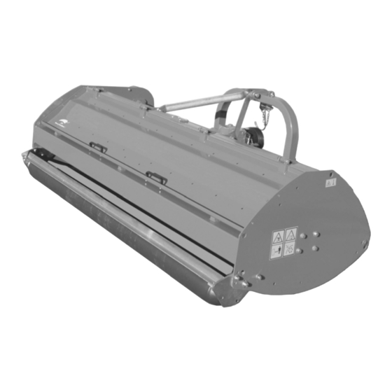
OPERATOR'S MANUAL
Shredders
JN009BGB F
- English - 07-2007
Table of
Contents
Previous
Page
Next
Page
1
2
3
4
5
Advertisement
Table of Contents
Need help?
Do you have a question about the BK230 and is the answer not in the manual?
Ask a question
Questions and answers
Related Manuals for KUHN BK230
Paper Shredder KUHN BKE 280 SUPER Operator's Manual
(72 pages)
Paper Shredder KUHN BKE 305 SUPER Operator's Manual
(72 pages)
Paper Shredder KUHN BK280 Operator's Manual
Bk series shredders (72 pages)
Paper Shredder KUHN BK320 Operator's Manual
Bk series shredders (72 pages)
Paper Shredder KUHN BKE150 Operator's Manual
(64 pages)
Paper Shredder KUHN BKE180 Operator's Manual
(64 pages)
Paper Shredder KUHN BKE210 Operator's Manual
(64 pages)
Paper Shredder KUHN BKE250 Operator's Manual
(64 pages)
Paper Shredder KUHN WMU 210 Assembly & Operators Manual
(37 pages)
This manual is also suitable for:
Bk280
Bk320
Table of Contents
Print
Rename the bookmark
Delete bookmark?
Delete from my manuals?
Login
Sign In
OR
Sign in with Facebook
Sign in with Google
Upload manual
Upload from disk
Upload from URL


Need help?
Do you have a question about the BK230 and is the answer not in the manual?
Questions and answers