Table of Contents
Advertisement
Quick Links
A421 Series Electronic Temperature Controls with
Cycle Timer
Installation Instructions
A421ABT-x, A421AET-x
Applications
IMPORTANT: Use this A421 Series Electronic
Temperature Control only as an operating control.
Where failure or malfunction of the A421 control could
lead to personal injury or property damage to the
controlled equipment or other property, additional
precautions must be designed into the control
system. Incorporate and maintain other devices, such
as supervisory or alarm systems or safety or limit
controls, intended to warn of or protect against failure
or malfunction of the A421 control.
IMPORTANT: Utiliser ce A421 Series Electronic
Temperature Control uniquement en tant que
dispositif de régulation. Lorsqu'une défaillance ou un
dysfonctionnement du A421 control risque de
provoquer des blessures ou d'endommager
l'équipement contrôlé ou un autre équipement, la
conception du système de contrôle doit intégrer des
dispositifs de protection supplémentaires. Veiller
dans ce cas à intégrer de façon permanente
d'autres dispositifs, tels que des systèmes de
supervision ou d'alarme, ou des dispositifs de
sécurité ou de limitation, ayant une fonction
d'avertissement ou de protection en cas de
défaillance ou de dysfonctionnement du
A421 control.
The A421 Series Electronic Temperature Controls are
single-stage, electronic temperature controls with a
single-pole, double-throw (SPDT) output relay.
A421 controls feature a backlit LCD with adjustable
brightness and three-button touchpad interface that
can be set up to restrict user adjustments. An LED
indicates the output relay's On/Off status.
A421 Series Electronic Temperature Controls with Cycle Timer Installation Instructions
Refer to the
QuickLIT website
A421 Control with Cycle Timer also provides sensor
offset capability and restricted user adjustment. The
temperature control range is -40 to 212°F or
-40 to 100°C.
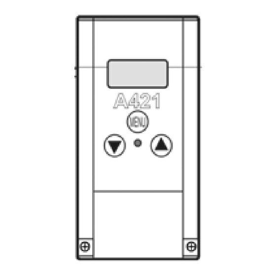
The A421 controls are available either in Type 1
(NEMA), IP20 (CE), high-impact plastic enclosures
suitable for surface or DIN rail mounting (Figure 1)
or in Type 4X (NEMA), IP66 (CE) watertight, corrosion
resistant surface mount enclosures (Figure 2).
The control housing base on the Type 4X/IP66 models
can be easily rotated 180º relative to the control
housing cover and LCD, allowing you to bring the
electrical connection to either the top or bottom of the
mounted control. Do not twist the wiring harness
between the housing base and cover more than 180º.
Dimensions
Figure 1: A421ABT Control with Type 1 (NEMA),
IP20 Enclosure; Dimensions, in. (mm)
1
Part No. 24-7664-3043, Rev. B
Issued March 2016
for the most up-to-date version of this document.
Advertisement
Table of Contents

Summary of Contents for Penn A421ABT series
- Page 1 A421 Series Electronic Temperature Controls with Cycle Timer Part No. 24-7664-3043, Rev. B Installation Instructions Issued March 2016 A421ABT-x, A421AET-x Refer to the QuickLIT website for the most up-to-date version of this document. Applications A421 Control with Cycle Timer also provides sensor offset capability and restricted user adjustment.
- Page 2 Observe the following guidelines when locating and Parts Included mounting an A421 control: Each A421 Control includes a Johnson Controls/ PENN® A99 Series temperature sensor. See A99 • Ensure that the mounting surface can support the Series Temperature Sensors, Wiring, and Technical control, DIN rail, mounting hardware, and any Specifications for more information about A99 sensors.
- Page 3 • Do not mount the control on surfaces that are On Type 4X models, select the knockout to be prone to vibration or in a location where removed. Place a screwdriver blade on the knockout high-voltage relays, motor starters, other sources near the edge.
- Page 4 Table 1: Maximum Recommended Sensor Cable IMPORTANT: Run all low-voltage wiring and Lengths and Wire Sizes cables separate from all high-voltage wiring. Wire Shielded cable is strongly recommended for input Maximum Sensor Cable Length Gauge (sensor) cables that are exposed to high Feet (Meters) electromagnetic or radio frequency noise.
- Page 5 Figure 4: Wiring the A421 Series Controls Using the Same Power Source to Power the Control Operation and Power the Controlled Equipment Table 2: A421 Control Wiring Terminals and Wire Size Information (Part 1 of 2) Terminal Label Description, Function, and Requirements Recommended Block Wire Sizes...
-
Page 6: Setup And Adjustments
Table 2: A421 Control Wiring Terminals and Wire Size Information (Part 2 of 2) Terminal Label Description, Function, and Requirements Recommended Block Wire Sizes Detects a switch closure between the BIN and COM terminals and 22 AWG (0.34 mm overrides the control to turn the fan on. Normal control resumes after this stranded, shielded switch is opened again. - Page 7 The range of usable temperature values is -40 to Sensor Offset Adjustment (So): Sensor offset allows 212°F or -40 to 100°C in 1° increments. you to compensate for any difference between the displayed temperature value and the temperature Restricted Adjustment Mode: The HtS and LtS sensed at the A99 sensor.
-
Page 8: A421 Control Parameter Setup Menus
Table 3: Standard Parameter Setup Codes, Descriptions, Range of Values, and Default Values (Part 2 of 2) Parameter Parameter Description (Menu) Range of Usable Values Factory Default Code Value Sensor Offset Adjustment (Advanced) -5 to 5ºF (-3 to 3ºC) 0ºF Sensor Failure Action (Basic and Advanced) 0 = output relay de-energized 1 (output relay... - Page 9 Viewing and Changing Values in the Basic Menu To access the Basic menu and view and change the Basic parameter values, follow these steps: 1. With the Main screen displayed, press MENU. The LCD displays OFF, which is the first parameter code screen displayed in the Basic menu.
-
Page 10: A421 Series Control With Free-Cooling Ventilation
Viewing and Changing Values in the Advanced • The fan relay goes Off when the sensed Menu temperature is less than or equal to the OFF value. To access the Advanced menu and view and change • If the temperature based On-time (t1+t2) is less the parameter values, follow these steps: than Ont, only the remaining Ont [Ont minus (t1+t2)] is enforced at the end of the cP. - Page 11 4. Select the Minimum Relay On-time (Ont) per cycle Note: The Ltt parameter is enforced (and the Ont is period (cP) when the sensed temperature remains ignored) whenever the sensed temperature falls below greater than LtS. the LtS value (even momentarily) during a given cycle period.
- Page 12 Restricting User Adjustment Setting the Control to Restricted Adjustment Mode You can restrict user adjustment of the A421 control to To set up the restricted adjustment feature: either just OFF value (control band) adjustment within 1. Ensure that the A421 is not in the restricted mode a defined range (Figure 9) or no user adjustment at all.
-
Page 13: Fault Codes
5. Press and simultaneously to return to the Troubleshooting Main screen. Fault Codes A421 Series controls display fault codes on the LCD as described in Table 4. Figure 11: Adjusting Temperature in the Restricted Menu Table 4: Fault Codes Defined Fault Code Definition System Status... -
Page 14: Repair Information
A99 sensors, mounting hardware, and other accessories used to install A421 controls. Contact your c. Reconnect the sensor leads and supply power nearest Johnson Controls/PENN distributor or sales to the control. representative to order these products. d. Replace the cover. -
Page 15: Technical Specifications
Table 6: A99 Temperature Sensors Selection Chart (Part 2 of 2) Product Code Description A99BB-300C PTC Temperature Sensor: Standard probe 2 in. (5.1 cm) with 9.8 ft (3.0 m) PVC cable; Ambient operating temperature range: -40 to 212ºF (-40 to 100ºC) A99BB-400C PTC Temperature Sensor: Standard probe 2 in. - Page 16 Table 8: A421 Series Electronic Temperature Controls (Part 2 of 2) Sensor Offset Range ±5ºF or ±3ºC Enclosure Material Type 1, IP20 High-Impact Thermoplastic or Type 4X, IP66 Watertight, Corrosion-Resistant, High-Impact Thermoplastic Note: To Maintain Type 4X / IP66 Rating, Tighten Enclosure Screws to: 10-12 in·lb Compliance North America: cULus Listed;...
- Page 17 Building Efficiency 507 E. Michigan Street, Milwaukee, WI 53202 Johnson Controls® and PENN® are registered trademarks of Johnson Controls, Inc. in the United States of America and/or other countries. All other trademarks used herein are the property of their respective owners. © Copyright 2016 by Johnson Controls, Inc. All rights reserved.
Need help?
Do you have a question about the A421ABT series and is the answer not in the manual?
Questions and answers