Advertisement
50048742:Rev.B
03/03/2011
09:18
Page 1
®
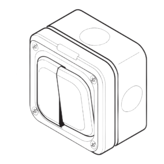
Masterseal Plus™
Switch Modules, Enclosures,
Neon Indicator Modules,
Junction Boxes,
Rated to IP66*
Contents
Page
A Product Features
2
B Service Ite ms
3
C Safety Instructions
4
D Installation
5
14
14
16
17
Figure 1
Please leave this leaflet with the end user for future reference
7. Please note; the colour codes used rigid cabling in the UK prior to April
2004 are as follows:-
RED = terminals marked 'L'
BLACK = terminals marked 'N'
GREEN / YELLOW = terminals marked '
'.
In all other areas of the EU, as well as new build installations in the UK
after April 2004, the colour codes used are:-
BROWN = terminals marked 'L'
BLUE = terminals marked 'N'
GREEN / YELLOW = terminals marked '
'
8. Use cable with a maximum outside diameter of 17mm.
9. PVC Cable Entry (see Service Items) must only be used at the bottom cable
entry of the enclosure.
6
A. PRODUCT FEATURES
The Masterseal Plus range consists of various surface mounted and flush
mounted products and associated bezels and service items.
The Masterseal Plus range of products are robust and made from a tough
thermoplastic material suitable for interior and exterior use wherever corrosion
resistance, dirt and moisture proofing is required.
All products accept MK push in conduit and cable entries that complement the
range. See Service Items.
All enclosures with external switch rockers have a fluorescent neon locator that
remains lit regardless of the switch position. Replacement neon locators are
available, see Service Items.
If correctly installed, the Masterseal Plus range of products offer an
international protection code of IP66*.
If you are in any doubt regarding this range of products, please contact MK
Technical Sales Service Department on:
+44 (0) 1268 563720 or your local MK representative.
All products conform to their relevant National standard as well as the
standard for enclosures BSEN60439-1, switches to BSEN60669-1and junction
box to BS6220.
*Applies to all products except the Grid Plus enclosure K56414
2
INSTRUCTIONS:
CAUTION
Do not allow paint or wood preservative to come into contact with
the product. The product can be safely mounted on painted surfaces
or surfaces treated with wood preservative when the paint or wood
preservative is completely dry.
1. Read the safety instructions.
2. Mark the position of the fixing holes for the mounting box:
77.5 mm
Centre
Line of
52.5mm
Conduit or
Cable
Entry
Figure 2
7
B. SERVICE ITEMS
List No.
Description
Dimensions
56890
Neon Locator
31 x 7 dia
56460
Entry Blank
26.9 dia x 5.25
56461
PVC Cable Entry
26.9 dia x 10.15
56462
20 mm Plain Conduit Entry
26.9 dia x 28
56463
20 mm Threaded conduit Entry
26.9 dia x 28
56464
Box Coupler
26.9 dia x 16.5
9933
M20 Earth Lead Adaptor
3
3. Drill holes and fit wall plugs suitable for a No. 8 wood screw.
4. Prior to fitting the mounting box to the wall, drill out the drain hole if
required (see Installation Note 3). File out the complete drain hole profile.
Take care not to damage the internal wall.
5. Carefully remove the cable entry blanks, or drill out rear cable entry, as
required and fit conduit entry (see Service Items).
Conduit Entry
Entry Blank
T O
P
Drill Out Feature
Drain Hole
Mounting
5 mm
Box
Drill Bit
Figure 3
8
C. SAFETY INSTRUCTIONS
WARNING
SWITCH OFF AND ISOLATE THE MAINS SUPPLY BEFORE CARRYING OUT
INSTALLATION OF THE MASTERSEAL PLUS PRODUCT.
1. This product must be installed by a competent person in accordance with
the current editions of the IEE Wiring Regulations (BS7671) and Buildings
Regulations. If in any doubt, consult a qualified electrician.
2. It is essential that all connections are made as instructed that cables are not
stressed and terminals are fully tightened.
3. Where an earth terminal is fitted this should be connected to a protective
earth conductor.
4. If metal conduit is used in more than one cable entry earth continuity must
be maintained between conduits.
5. The neon locator must not be used as a mains status indicator.
6. In junction boxes, four terminal blocks are provided (L, N, E and Loop as
required). Ensure only wires of the same polarity are connected in each
block. Earth and Loop terminals in the mounting box should not be used.
7. At the end of their useful life, the packaging and product should be
disposed of via a suitable recycling centre where facilities exist. DO NOT
BURN.
4
6. Secure the mounting box to wall with four No. 8 wood screws. Position
drain hole at bottom left hand corner.
7. Align and install conduit or conduit entry as required.
8. Seal the conduit and cable entry with a non setting conduit sealant such as
Egaweld™ No. 2. Refer to Figure 4.
Conduit
Sealant
Conduit
Entry
No 8 Wood Screw
Mounting Box
Drain Hole
Figure 4
9
D. INSTALLATION
NOTES:
1. The enclosure is made from polycarbonate which is a highly durable
material, and ideal for most environments. However, if installing in areas
where creosote, some chemicals, synthetic oils and harsh cleaners are used,
seek advice from MK Technical Sales Service Department
2. The enclosure must be mounted on a flat, vertical surface that is free from
grease, dirt and loose material.
3. If the conduit cable entry is from the top or sides the lower drain hole in
the mounting box must be drilled out using a 5mm diameter drill bit. This
will allow any condensation formed in the conduit system to drain out of
the unit. Note: opening the drain hole will reduce the IP rating;
therefore ensure that jetted water is not directed at the unit.
4. The drain hole should not be drilled out if the enclosure is to be installed in
an excessively dusty environment. If the drain hole is not drilled out, only
the bottom cable entry must be used.
5. If conduit is used for bottom cable entry, a 5 mm diameter drain hole
needs to be drilled in the lowest point of the conduit run.
6. If wiring directly to the enclosure without conduit and the installation is
outdoors, ensure that a cable specified for outside use is used.
5
Switch and Neon Modules
9. Locate and clip the appropriate switch modules into position on the front
plate as shown in Figure 5.
10. Locate the slots at the TOP of the switch module over the locating lugs at
the TOP of the front plate and press the bottom of the switch module
firmly to snap it into place. TOP is marked on the moulding of the switch
module and the front plate.
11. When a neon module is fitted ensure the module is fitted on the left hand
side (i.e. behind the window in the front plate).
Locate Module
on lugs
Press to snap
into place
Figure 5
10
Advertisement
Table of Contents

Summary of Contents for MK Electric Masterseal Plus 56890
- Page 1 50048742:Rev.B 03/03/2011 09:18 Page 1 ® Masterseal Plus™ A. PRODUCT FEATURES B. SERVICE ITEMS C. SAFETY INSTRUCTIONS D. INSTALLATION WARNING Switch Modules, Enclosures, The Masterseal Plus range consists of various surface mounted and flush NOTES: SWITCH OFF AND ISOLATE THE MAINS SUPPLY BEFORE CARRYING OUT mounted products and associated bezels and service items.
- Page 2 Fax: +44 (0) 1268 563365 (International) MK Electric Limited wishes to make it clear that it owns all the original designs email: mkorderenquiries@honeywell.com of the products that it manufactures (whether or not listed in this leaflet) and that it will take all necessary action in any part of the world against any party web site: www.mkelectric.co.uk...
Need help?
Do you have a question about the Masterseal Plus 56890 and is the answer not in the manual?
Questions and answers