
Related Manuals for Foxjet SoloSeries 45

Summary of Contents for Foxjet SoloSeries 45
- Page 1 Operations Manual Thermal Jet Ink Jet System 5780-329 Revision J 1 Missouri Research Park Drive • St. Charles, MO 63304 • 1-800-369-5384 Illinois Tool Works Inc © 2010...
- Page 2 5780-329 Revision J Ink Cartridge: The SoloSeries has been engineered and designed to work with Foxjet ink cartridges. The SoloSeries’ Smart Level Ink Detection System, which provides ink level monitoring to ensure com- plete ink usage and product safety, will not be func- tional if used with non-Foxjet ink cartridges.
- Page 3 The inks and conditioners used with the SoloSeries Thermal Jet system carry a limited warranty. For all warranty terms and conditions, contact Foxjet an ITW Company for a complete copy of the Limited Warranty Statement.
-
Page 4: Table Of Contents
Thermal Jet Section 1: Safety and Ink Cartridge Usage ........1 Section 2: Quick Start .. - Page 5 Thermal Jet Appendix D: File Backup and Restore ......... . . 44 File Backup .
-
Page 6: Section 1: Safety And Ink Cartridge Usage
Store inks and solvents under the recommended conditions found on the MSDS (Material Safety Data Sheet). Ink Cartridge: The SoloSeries has been engineered and designed to work with Foxjet ink cartridges. The SoloSeriess’ Smart Level Ink Detection System, which provides ink level monitoring to ensure complete ink usage and product safety, will not be functional if used with non-Foxjet ink cartridges. -
Page 7: Section 2: Quick Start
Thermal Jet Section 2: Quick Start Section 2: Quick Start Optional Marksman HHI controller TYPICAL INSTALLATION Contents: • SoloSeries Print Head • Bracketry Kit • Power Supply, 15 V • Power Supply Bracket • Power Cord • Software CD 5780-329 Operations Manual Rev J Page 2... -
Page 8: Step 1: Assemble Bracketry
Thermal Jet Section 2: Quick Start Step 1: Assemble Bracketry Step 2: Assemble Bracketry to Conveyor 5780-329 Operations Manual Rev J Page 3... -
Page 9: Step 3:Assemble Soloseries Print Head And Power Supply To Bracketry
Thermal Jet Section 2: Quick Start Step 3:Assemble SoloSeries Print Head and Power Supply to Bracketry Ensure bar is behind front face of print head 5780-329 Operations Manual Rev J Page 4... -
Page 10: Step 4: Adjust Soloseries Print Head To Substrate
Thermal Jet Section 2: Quick Start Step 4: Adjust SoloSeries Print Head to Substrate Adjust print head vertically to meet requirement. Adjust print head horizontally to set print gap. .1" (2.5mm) GAP ADJUST THE PRINT RECOMMENDED HEAD TO THE SUBSTRATE WITH THIS BRACKET 5780-329 Operations Manual Rev J Page 5... -
Page 11: Step 5: Insert Cartridge Pen Into Print Head
Thermal Jet Section 2: Quick Start Step 5: Insert Pen Cartridge into Print Head PEN STOP Rotate Cover Open Insert Pen Cartridge at an angle up to Pen Stop PEN STOP When inserting cartridge, aim nose at an angle towards black pogo pin component. Slide pen cartridge up to Pen Stop. -
Page 12: Step 6: Cabling, Power, And Serial Port Setup
Thermal Jet Section 2: Quick Start Step 6: Cabling, Power, and Serial Port Setup Cabling CAUTION: Power should be disconnected from the print head prior to connecting or dis- connecting any external device, including: PC, controller, or print head daisy chain cables. Electrical arcing may occur if external cabling is connected or disconnected while power is supplied to the unit. - Page 13 Thermal Jet Power CAUTION: Power should be disconnected from the print head prior to connecting or dis- connecting any external device, including: PC, controller, or print head daisy chain cables. Electrical arcing may occur if external cabling is connected or disconnected while power is supplied to the unit.
- Page 14 Thermal Jet Press the System Setup button, and then the Serial Ports tab. To ensure the baud rate is set for 57600, press the button beneath the Port/Baud column and adjust if necessary. Press the OK button to exit the Serial Port Setup screen. If "Serial Print Head: Task x"...
-
Page 15: Step 7: Configure The Print Head
Thermal Jet Step 7: Configure the Print Head On the home screen, press the Control Panels button, and then press the System Setup button. On the Print Heads page press the Redo Print Head Setup button. Select the desired direction. Select the number of print heads, identify the first in the daisy chain, and select the appro- priate print head type by touching each one and then the drop down box. -
Page 16: Step 8: Create A Message
Thermal Jet Step 8: Create a Message From the home screen, select the Messages button and then the New button to enter the message editor. Create and save the message, and then exit the message editor. Product Side Quick Save Product Setup File Menu Message... -
Page 17: Step 9: Print A Message
Thermal Jet Step 9: Print a Message From the home screen, push the Print button. Select the desired message to print, and push the Print It button. The message will print on the next photocell trigger. 5780-329 Operations Manual Rev J Page 12... -
Page 18: Section 3: Marksman Hhi Or Gui Functionality
Thermal Jet Section 3: Marksman HHI or GUI Functionality Section 3: Marksman HHI or GUI Functionality Keypad or Keyboard BACKSPACE POWER SCREEN BRIGHTNESS ESC (Escape): • Closes the current window, a dialog box, or menu. • Restores the original contents of any input entry box, if Enter has not been pressed. Arrow Keys: •... -
Page 19: Home Screen
Thermal Jet Home Screen Zoom Button Print Head Daisy Chain Identifier Task 2 Message Select Window Button Task 1 Task 2 Select Print / Pause Button Button Task 1, Task 2 Status Screen Ink Status Access Button Task 1 Print / Pause Print Counts Variable Field Button... - Page 20 Thermal Jet Quick Print Menu Button: • Allows one to access the Print dialog box directly, even with Restricted User Access enabled. • Simply select the desired message and press the Print It button. The message will print at the next photocell trigger.
-
Page 21: Main Menu
Thermal Jet Main Menu Main Menu Collapsed Main Menu Expanded Print Menu Print Menu Button Cancels print immediately after a confirmation popup dialog box Closes this menu immediately NOTE: The Variable Field button is not available. In order to Fires all jets for a short update a variable field, reselect period of time on the Returns to Home... - Page 22 Thermal Jet Message Editor Reverts message to the last saved File Menu Clears contents of message editor Quick save Calculates of current estimated ink message usage for the contents of the editor Prints the contents Message of this editor on the display next photocell area...
- Page 23 Thermal Jet Message Editor continued: User Defined Time Codes When User Defined selected, Define Time Code button appears Sequential format: minute code shown. Minute 00 = AA, 01 = AB, 02 = AC, etc. Tabular format: codes printed taken from Periodic format: example above illustrates a table.
- Page 24 Thermal Jet Message Editor continued: User Defined Date Codes When User Defined selected, Define Date Code button appears The Fortnight code Sequential format: in example above type is available for Sunday = ’A’, Monday = B, etc the Tabular format only Tabular format: codes printed taken from table.
- Page 25 Thermal Jet Message Editor continued: Product Counts, Variable Fields, Logos Maximum 9-digit count Scroll through logo images or select from list Variable Field Data Source User: Print data entered when print message containing the variable field is selected to print. COM1, COM2: Data is received though COM1 or COM 2 serial port.
- Page 26 Thermal Jet Message Editor continued: Bar Codes Bar Code Data Source Fixed: Data entered when the bar code is created. Properties dialog for User: Data entered when print Data Matrix code message containing bar code is selected to print. Dummy data entered when the bar code is created acts as a place holder.
-
Page 27: Control Panels Menu
Thermal Jet Control Panels Menu Controls print head and I/O feature not ancillary equipment available on configuration Marksman HHI Configures network System Utilities connectivity via the menu for miscella- Ethernet port neous controller tools and file man- agement Language and unit of measure configuration Security Access Closes this menu... - Page 28 Thermal Jet Network: Does not apply to Thermal Jet print heads Regional Settings: User Access: Controls within this box set the user access level. Buttons outside the box mirror the Home Screen and indicate which functions are password protected and which are open. Padlock symbol indicates function is password pro-...
-
Page 29: Time & Date Setting Screens
Thermal Jet Utilities: After performing the Restore default configu- ration function, the serial port must be reconfigured for a serial print head. Time & Date Setting Screens 5780-329 Operations Manual Rev J Page 24... -
Page 30: Status Screen
Thermal Jet Status Screen Note: This set of status screens represents three print heads, two SoloSeries45 and a SoloSeries90, setup in a daisy chain. The first two print heads (Head 1 & 2) are properly connected and detected. The third print head has not been properly connected to the daisy chain. -
Page 31: Section 4: Maintenance & Shutdowns
• Deionized or distilled water (DO NOT USE TAP WATER) for POROUS INK ONLY • Sponge Swabs (Foxjet p/n: 5760-832) Procedure: 1. For POROUS INK ONLY cartridges, lightly dampen sponge swab with deionized water. 2. For NON-POROUS INK ONLY cartridges, hold sponge swab against orifice array of cartridge. -
Page 32: Weekly To Monthly Maintenance, Print Head
For extended shutdowns, follow the Daily Maintenance procedure, PEN CARTRIDGE remove the ink cartridge from the print head and store in the optional Cartridge Boot Cap (Foxjet Kit p/n: 5780-208). CARTRIDGE BOOT CAP 5780-329 Operations Manual Rev J Page 27... -
Page 33: Section 5: Troubleshooting
Red LED is flashing slowly • Pen cartridge is out of ink • Prepare to install a new pen cartridge. and significant print deg- • Install an original Foxjet cartridge. radation is imminent. • A non-Foxjet cartridge is installed. Red LED is flashing fast •... -
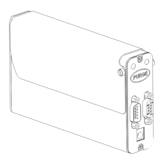
Page 34: Appendix A: Specifications
Thermal Jet Appendix A: Specifications Appendix A: Specifications SoloSeries45: 6.23 in 1.32 in [158.2 mm] [33.6 mm] 5.30 in [134.6 mm] (BULK INK ONLY) 3.65 in [92.6 mm] 0.87 in 2X M6 X 1.0 X x .16 in [4.06 mm] 0.90 in [22.9 mm] [22.1 mm] PROVIDED FOR PRINT... -
Page 35: Soloseries90
Thermal Jet Appendix A: Specifications SoloSeries90: 2.43 in 6.20 in [61.8 mm] [157.4 mm] 5.81 in [147.5 mm] (BULK INK ONLY) 4.13 in [104.9 mm] 1.38 in [35.2 mm] 0.90 in 0.87 in [22.1 mm] 2X M6 X 1.0 X.16 in [4.06 mm] [22.8 mm] LOWEST PROVIDED FOR PRINT... -
Page 36: Soloseries Is
Ink Type Dye base Ink Cartridge: The SoloSeries has been engineered and designed to work with Foxjet ink cartridges. The Solo- Series’ Smart Level Ink Detection System, which provides ink level monitoring to ensure complete ink usage and product safety, will not be functional if used with non-Foxjet ink cartridges. -
Page 37: Marksman Hhi
Thermal Jet Appendix A: Specifications Marksman HHI: Weight 1.8 lbs (0.82 kg) User Interface Type: Graphical User Interface Keyboard: 70-key, QWERTY style, elastomeric keyboard 800 X 480 color LCD with touch screen, 7.0" (177.8 mm) diagonal Fonts Arial 30, 75, 150, 225, and 300 (0.1in / 2.5 mm, 0.25 in / 6.3 mm, 0.5 in / 12.7 mm, 0.75 in / 19.05 mm, and 1 in / 25.4mm). -
Page 38: Appendix B: Theory Of Operation
Data Matrix 2-D codes. Unlike other Foxjet inkjet technologies, the SoloSeries print heads store and process the currently printing message internally. This allows the print heads to be disconnected from the controlling device and operate "stand alone"... -
Page 39: Marksman Hhi
Thermal Jet Appendix B: Theory of Operation Marksman HHI Functional Description The Marksman HHI Ink Jet System prints text, autocodes (such as product counts or time and date stamps), bar codes, and/or graphics onto products as they travel by conveyor past stationary print heads. - Page 40 Thermal Jet Single task with accessory hub: The Marksman HHI draws its power from the daisy chain, and is plugged into the ’hand held’ connector on the accessory hub; the accessory hub is plugged into the last print head in the daisy chain.
- Page 41 Thermal Jet Dual task with accessory hub: The Marksman HHI draws its power from the task 1 daisy chain; COM1 is Dual task: The Marksman HHI draws connected to the ’hand held’ connector on the acces- its power from the task 1 daisy chain; sory hub, and the accessory hub is then connected to COM1 is connected to the last print the last print head in the task 1 daisy chain.
- Page 42 Thermal Jet Dual task with optional desktop power supply: The Marksman HHI COM1 port is connected to the first print head in the task 1 daisy chain, and COM2 is connected to the first print head in the task 2 daisy chain. If either task uses the accessory hub it is connected to the last print head in the daisy chain.
-
Page 43: Interconnect Diagram
Thermal Jet Interconnect Diagram Marksman HHI Controller CPU Diagram 5780-329 Operations Manual Rev J Page 38... -
Page 44: Appendix C: Part Numbers - Consumables And Service Parts
Ink Cartridge: The SoloSeries print head has been engineered and designed to work with Foxjet ink cartridges. The SoloSeries’ Smart Level Ink Detection System, which provides ink level moni- toring to ensure complete ink usage and product safety, will not be functional if used with non-Foxjet ink cartridges. - Page 45 Thermal Jet Appendix C: Part Numbers - Consumables and Service Parts SoloSeries90 Item Kit No. Description 5760-302 Power Supply, Print Head SoloSeries90 Complete Print Head Kit with Mounting Bracketry, Power 5780-007FX Supply, Data Cable, & PC Software 5780-225FX Cover, Enclosure, Standard 5780-225BIFX Cover, Enclosure, Bulk Ink 5780-221FX...
- Page 46 Thermal Jet Appendix C: Part Numbers - Consumables and Service Parts Marksman HHI Item Kit No. Description 5780-015FX Marksman HHI Controller 5780-232 Color Display Replacement 5780-233 CPU PCB Replacement Bracketry Item Kit No. Description 5780-234 Bracketry, Marskman HHI Mounting 5780-200 Bracketry, SoloSeries Print Head Mounting 5780-227 Bracketry, Print Down...
-
Page 47: Optional Equipment
Thermal Jet Appendix C: Part Numbers - Consumables and Service Parts Optional Equipment Encoder, Photocell, Accessory Hub, and Beacon Item Kit No. Description 5760-820-IJ Encoder Assembly with Mounting Bracket & 25’ Cable 5765-206 Encoder O-ring Replacement 5760-383 Photocell 5780-010FX Accessory Hub with Power Supply 5780-214 Beacon ‘... - Page 48 Thermal Jet Appendix C: Part Numbers - Consumables and Service Parts Roller & Retractor Bracketry Item Kit No. Description 5780-206 Roller Bracket Only 5780-207 Roller and Retractor Bracket Roller & Retractor Bracketry Roller Bracket Only Maintenance Item Kit No. Description 1901-398 Hand Cleaner, Reduran 5760-832...
-
Page 49: Appendix D: File Backup And Restore
Thermal Jet Appendix D: File Backup and Restore Appendix D: File Backup and Restore Use these procedures for making archival copies of the system configuration and print message files, and for preserving the system's configuration and print messages during firmware upgrades. File types saved during a backup are .cfg, .prd, .bmp and .alp. These are the system configuration files, message files, logo files and label files, respectively. -
Page 50: File Backup
Thermal Jet Appendix D: File Backup and Restore File Backup To backup the sys- tem files, click the Backup files link. dialog shown at right (or a similar dialog box) will appear. Click the Save button. A Save As dialog appears. The Marksman HHI files backed up are compressed and put into a single file, and are given the default name and file extension backup.tgz . -
Page 51: Restoring Backed-Up Files
Thermal Jet Appendix D: File Backup and Restore Restoring Backed-Up Files To restore the controller’s backed up system files, click the Restore files from backup link. The web page shown below appears. Click the Browse... button to locate and select the backup file to be sent to the controller. Click the Restore button to send the file to the controller. -
Page 52: Appendix E: Configuring A Pc To Communicate With The Ij3000-Es
Thermal Jet Appendix E: Configuring a PC to Communicate with Marks- Appendix E: Configuring a PC to Communicate with Marksman HHI This appendix has instructions for setting the IP address and subnet mask of the PC so it can communicate with the Marksman HHI Controller. Included are instructions for Windows XP®, Windows 2000®, Windows 98®, and Windows 95®. - Page 53 Thermal Jet Appendix E: Configuring a PC to Communicate with Marks- 3. Select Internet Protocol (TCP/IP) then click Properties button. 4. Click the Use the following IP address radio button. Enter an IP address of 10.1.2.4 , a subnet mask of 255.255.255.0 , click the OK button.
-
Page 54: Windows 2000
Thermal Jet Appendix E: Configuring a PC to Communicate with Marks- Windows 2000® 1. Open the Start menu; select Settings , then Network and Dial-up Connections. 2. Click the desired connection, then open the File menu and select Properties . 5780-329 Operations Manual Rev J Page 49... - Page 55 Thermal Jet Appendix E: Configuring a PC to Communicate with Marks- 3. Select Internet Protocol (TCIP/IP) then click Properties button. 4. Click the Use the following IP address radio button. Enter an IP address of 10.1.2.4 , a subnet mask of 255.255.255.0, and click the OK button.
-
Page 56: Appendix F: Font Samples
Thermal Jet Appendix F: Font Samples Appendix F: Font Samples Arial 30 - 1/10 in (2.54 mm): AaBbCcDdEeFf 1234567890 Arial 75 - 1/4 in (6.35 mm): AaBbCcDdEeFf 1234567890 Arial 150 - 1/2 in (12.7 mm): AaBbCcDdEeFf 1234567890 For best results printing the next two fonts use an external encoder. The top images were printed with an external encoder. -
Page 57: Appendix G: Creating Logo Files
Thermal Jet Appendix G: Creating Logo Files Appendix G: Creating Logo Files Open Paint from a PC by selecting Start, Programs, Accessories, and then Paint. Bring up the Attributes dialog box by selecting Image and then Attributes . Enter the Width and Height of the logo in Pixels . For practical purposes the maximum height of a logo is150 pixels if the logo is prined with a SoloSeries45 print head, and 300 pixels if printed with a SoloSeroes90 print head. - Page 58 Thermal Jet Appendix G: Creating Logo Files Define the pixels of the logo using the drawing tools, or copy and paste an image from another document. Bring up the Flip and Rotate dialog by selecting Image , Flip/Rotate . Select Rotate by angle , then 270° . Click Ok . From the File Menu , select Save As and save the logo in a directory location that you will remember.
-
Page 59: Appendix H: Uploading Files To The Print Head And File Management
Thermal Jet Appendix H: Uploading Files to the Print Head and File Man- Appendix H: Uploading Files to the Print Head and File Management CAUTION: Power should be disconnected from the print head prior to connecting or dis- connecting any external devise, including: PC, handheld, controller or print head daisy chain cables. - Page 60 Thermal Jet Appendix H: Uploading Files to the Print Head and File Man- 3. Scroll to the bottom of the utilities list and select File manager . 4. Touch the Do Function button; the File Manager screen is displayed. The home folder contains all folders and files related to Marksman HHI operation; task folders, Task:1 and Task:2 (not shown), contain the font and logo files present on the print heads on their respective tasks.
- Page 61 Thermal Jet Appendix H: Uploading Files to the Print Head and File Man- Open the home folder. The display shows the available folders and files: The display shows a list of available files. Highlight the bmps folder with the up / down arrows and open it: Select the file to be uploaded to the print head(s), and then touch the Copy button.
- Page 62 Thermal Jet Appendix H: Uploading Files to the Print Head and File Man- Select and open the Task:1 folder. The display shows a list of all files on print head #1 only; it is assumed that all print heads have the same files. Open Touch the Paste button.
- Page 63 Thermal Jet Appendix H: Uploading Files to the Print Head and File Man- To remove a file from all print heads on a task: 1. Select and open the task folder. Open 2. Select the file to be deleted, and then touch the Delete button. Delete 3.
-
Page 64: Appendix I: Communicating Directly To The Print Head
Thermal Jet Appendix I: Communicating Directly to the Print Head Appendix I: Communicating Directly to the Print Head The 1/2" (12.7 mm) and 1" (25.4 mm) print heads can be controlled by direct serial commu- nication. Refer to the serial protocol document 5780-316N when communicating directly to the print head without the use of a controller or the pc GUI software interface. -
Page 65: Appendix J: Aligning The 1" (25.4 Mm) Print Head
Thermal Jet Appendix J: Aligning the 1" (25.4 mm) Print Head Appendix J: Aligning the 1" (25.4 mm) Print Head NOTE: This procedure assumes that the user has already installed the equipment per the installation procedure (See “Section 2: Quick Start” on page 2.). In addition, an encoder should be used for the best horizontal alignment between both print cartridges. -
Page 66: Appendix K: Soloseries Is Bulk Ink System
Thermal Jet Appendix K: Bulk Ink Supply Appendix K: Bulk Ink Supply Wear safety goggles when working with industrial inks and solutions! WARNING: Disconnect power during installation. CAUTION: Sudden impact to the installed print head (caused by moving the conveyor with the print system attached or moving the print system from one location to another) can cause ink to seep out the front of the print cartridge. - Page 67 Thermal Jet Appendix K: Bulk Ink Supply 2. Make ink line connections from the bulk ink supply to the regulator per the diagram below; the trunk line should be made as short as practical. (CAUTION: Do not con- nect septum fitting to the print cartridge at this time.) Tub ing, 1/8"...
- Page 68 Thermal Jet Appendix K: Bulk Ink Supply 4. Insert print cartridges into the print heads and a 350 ml ink cartridge in the bulk ink supply. 5. Bleeding air out of the ink lines: Valve a) At the ink service port of the trunk line, depress the valve of the fitting in short spurts into a rag or trash can.
- Page 69 Thermal Jet Appendix K: Bulk Ink Supply Setup for print down application The bracketry that comes standard with the print head does not accommo- date a print down setup. A separate bracket kit (5780-227) is available to allow for a print down setup. This kit includes tubing and fittings for extend- ing the tubing between the regulator and print head.
- Page 70 Thermal Jet Appendix K: Bulk Ink Supply 90° Tilt Setup The bulk ink supply allows the print head to be tilted 90° from vertical versus the 45° limita- tion with a standard print cartridge. The relative positioning between the reservoir and print head needs to be maintained for the print head to function properly.
- Page 71 Thermal Jet Appendix K: Bulk Ink Supply ● A red LED on the rear panel of the SoloSeries IS, and an optional beacon, indicate the sys- tem’s operational status: ○ LED/beacon is off - system is operating normally. ○ LED/beacon is on steady - normal system operating pressure (5 psi) was not achieved after 15 seconds of continuous pressure pump operation and the pump has shut down.
Need help?
Do you have a question about the SoloSeries 45 and is the answer not in the manual?
Questions and answers